Proportional Valve Servo Amplifier
AssemblyThe servo amplifier electronics connect an electrical command to movement of a proportional valve. In the modeled feedback arrangement, the command is compared with the position reported by LVDT feedback, and the drive electronics adjust the solenoid's actuation. The sensor reports position; the power stage supplies the electrical drive needed to change it.
The component list separates those jobs. A microcontroller handles the control logic, the feedback circuit conditions the sensor signal, and the driver stage controls the coil drive. The circuit board and passive components connect and support these functions. This is a functional breakdown, not a complete board schematic.
One practical distinction is a separate amplifier card versus electronics integrated into the valve. Moog's electronic-feedback valve overview describes onboard electronics that remove the need for an external controller card. Its direct-operated valve description also identifies closed-loop spool-position control. Controlling the spool is not the same as directly measuring every pressure, load, or actuator position elsewhere in the hydraulic system.
For a hydraulic test bench, that boundary matters when identifying which feedback signals the test needs. The generic board shown here is not a drop-in replacement specification. Command interface, coil requirements, feedback compatibility, tuning, and fault behavior depend on the exact valve and electronics combination.
Proportional Valve Servo Amplifier parts and their functions
5 top-level parts · 5 parts in total · full bill of materials below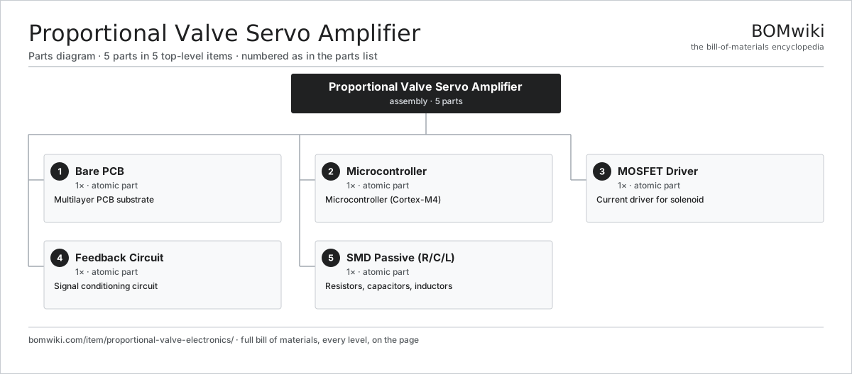
| # | Part | Qty | What it does |
|---|---|---|---|
| 1 | Bare PCB | 1× | Multilayer PCB substrate |
| 2 | Microcontroller | 1× | Microcontroller (Cortex-M4) |
| 3 | MOSFET Driver | 1× | Current driver for solenoid |
| 4 | Feedback Circuit | 1× | Signal conditioning circuit |
| 5 | SMD Passive (R/C/L) | 1× | Resistors, capacitors, inductors |
3D model
No 3D model yet. Have a CAD file of this? Add a 3D model. STL renders right on this page; STEP, FreeCAD, and OpenSCAD sources are welcome too (openly licensed, like all 3D models on BOMwiki).
Build & assembly graph
expand / collapse · shared sub-assemblies converge · links to related products · est. labourTap an assembly to expand/collapse · tap a part to open it · use “Open page” for any node · drag to pan, scroll to zoom.
Bill of materials for Proportional Valve Servo Amplifier
5 top-level lines · 5 rows shown · 5 parts total · indented to 3 levels| # | Item / sub-assembly | Part no. | Qty/assy | Ext. qty | Parts | Type |
|---|---|---|---|---|---|---|
| 1 | Bare PCB | pcb-bare | 1× | 1 | · | part |
| 2 | Microcontroller | mcu | 1× | 1 | · | part |
| 3 | MOSFET Driver | proportional-valve-electronics-mosfet | 1× | 1 | · | part |
| 4 | Feedback Circuit | proportional-valve-electronics-feedback | 1× | 1 | · | part |
| 5 | SMD Passive (R/C/L) | smd-passives | 1× | 1 | · | part |
Something wrong in this list? Report a problem with this BOM.
Where the proportional valve servo amplifier is used
2 products across 1 domain contain it, directly or inside a sub-assemblyUsed in 2 assemblies
Sourcing: possible vendors
Browse the supplier directory → Prices, MOQ, and lead times are algorithmic estimates, not quotes, and not claims about these companies. Company mappings are curated by keyword; est. price band $2–$500. How estimates work| Vendor | HQ | Specialty | MOQ | Lead time |
|---|---|---|---|---|
|
🇨🇳Inovance
inovance.com ↗
|
Shenzhen, CN | Drives & motion control | 500 units | 10–14 wks |
| sonacomstar.com ↗ | Gurugram, IN | EV driveline & motors | 500 units | 10–14 wks |
| broad-ocean.com ↗ | Zhongshan, CN | Electric motors | 500 units | 10–14 wks |
| nidec.com ↗ | Singapore | Motors, regional ops | 500 units | 10–14 wks |
| bosch.in ↗ | Bengaluru, IN | Automotive components | 500 units | 10–14 wks |
261-word article