Network Switch
ProductOverview
A network switch forwards Ethernet frames between devices on a local network at wire speed. This is a 48-port managed Layer-3 switch in a 1U rack chassis: it combines high-density gigabit copper access, 10G fiber uplinks, power-over-Ethernet for connected devices, and a routing engine that lets it move traffic between IP subnets without a separate router.
The Chassis is a steel rackmount case with EMI shielding and 19-inch rack ears. Inside, the Switching Mainboard carries the switching ASIC and control CPU, the Port Module presents the front-panel jacks and optics cages, and the PoE Subsystem injects power into the access ports. A passive Midplane links the mainboard to two hot-swap power supplies and the Fan Tray. A Front Panel Indicators board drives status LEDs and an OLED display.
How it works
When a frame arrives on a port, its copper PHY recovers the bits and hands them to the switching ASIC. The ASIC reads the destination MAC address and looks it up in a forwarding table held partly in TCAM, which resolves the lookup in a single clock cycle, then sends the frame out only the port where that device lives. Layer-3 traffic is matched against routing entries the same way, so the switch rewrites headers and forwards between subnets at line rate. The Control-Plane CPU runs the switch OS and routing protocols but stays off the data path; actual packet movement happens entirely in the ASIC, which is why a 1U box can forward 130 million packets per second. The PoE subsystem detects and classifies powered devices on each port, then delivers up to 30 W over the same cable that carries data, drawn from a shared 740 W budget.
Network Switch parts and their functions
9 top-level parts · 1,367 parts in total · full bill of materials below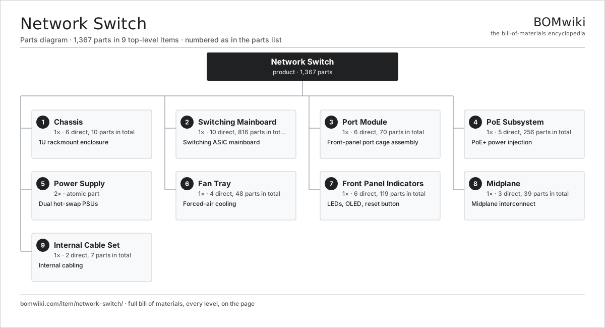
| # | Part | Qty | What it does |
|---|---|---|---|
| 1 | Chassis 6 parts | 1× | 1U rackmount enclosure |
| 2 | Switching Mainboard 10 parts | 1× | Switching ASIC mainboard |
| 3 | Port Module 6 parts | 1× | Front-panel port cage assembly |
| 4 | PoE Subsystem 5 parts | 1× | PoE+ power injection |
| 5 | Power Supply | 2× | Dual hot-swap PSUs |
| 6 | Fan Tray 4 parts | 1× | Forced-air cooling |
| 7 | Front Panel Indicators 6 parts | 1× | LEDs, OLED, reset button |
| 8 | Midplane 3 parts | 1× | Midplane interconnect |
| 9 | Internal Cable Set 2 parts | 1× | Internal cabling |
Diagrams & photos

3D model
No 3D model yet. Have a CAD file of this? Add a 3D model. STL renders right on this page; STEP, FreeCAD, and OpenSCAD sources are welcome too (openly licensed, like all 3D models on BOMwiki).
Build & assembly graph
expand / collapse · shared sub-assemblies converge · links to related products · est. labourTap an assembly to expand/collapse · tap a part to open it · use “Open page” for any node · drag to pan, scroll to zoom.
Bill of materials for Network Switch
9 top-level lines · 54 rows shown · 1,367 parts total · indented to 3 levels| # | Item / sub-assembly | Part no. | Qty/assy | Ext. qty | Parts | Type |
|---|---|---|---|---|---|---|
| 1 | Chassis 6 parts | network-switch-chassis | 1× | 1 | 10 | assembly |
| 1.1 | Sheet Metal Panel | sheet-panel | 4× | 4 | · | part |
| 1.2 | Front Bezel | network-switch-front-bezel | 1× | 1 | · | part |
| 1.3 | Rack Mount Ear | network-switch-rack-ear | 2× | 2 | · | part |
| 1.4 | EMI Shielding | network-switch-emi-shield | 1× | 1 | · | part |
| 1.5 | Grounding Lug | network-switch-ground-lug | 1× | 1 | · | part |
| 1.6 | Fastener Set | fastener-set | 1× | 1 | · | part |
| 2 | Switching Mainboard 10 parts | network-switch-mainboard | 1× | 1 | 816 | assembly |
| 2.1 | Bare PCB | pcb-bare | 1× | 1 | · | part |
| 2.2 | Compute SoC Module | soc-module | 1× | 1 | · | part |
| 2.3 | Control-Plane CPU | network-switch-cpu | 1× | 1 | · | part |
| 2.4 | DDR4 DRAM | network-switch-ram | 2× | 2 | · | part |
| 2.5 | NAND Flash | network-switch-flash | 1× | 1 | · | part |
| 2.6 | TCAM | network-switch-tcam | 1× | 1 | · | part |
| 2.7 | Ethernet PHY | network-switch-phy | 6× | 6 | · | part |
| 2.8 | Clock Generator | network-switch-clock-gen | 1× | 1 | · | part |
| 2.9 | Heatsink | network-switch-heatsink | 2× | 2 | · | part |
| 2.10 | SMD Passive (R/C/L) | smd-passives | 800× | 800 | · | part |
| 3 | Port Module 6 parts | network-switch-port-module | 1× | 1 | 70 | assembly |
| 3.1 | RJ45 Jack | network-switch-rj45-jack | 48× | 48 | · | part |
| 3.2 | Ethernet Magnetics | network-switch-magnetics | 12× | 12 | · | part |
| 3.3 | SFP+ Cage | network-switch-sfp-cage | 4× | 4 | · | part |
| 3.4 | Connector | connector | 4× | 4 | · | part |
| 3.5 | Console Port | network-switch-console-port | 1× | 1 | · | part |
| 3.6 | USB Port | network-switch-usb-port | 1× | 1 | · | part |
| 4 | PoE Subsystem 5 parts | network-switch-poe-subsystem | 1× | 1 | 256 | assembly |
| 4.1 | Bare PCB | pcb-bare | 1× | 1 | · | part |
| 4.2 | PoE Controller IC | network-switch-poe-controller | 6× | 6 | · | part |
| 4.3 | Power MOSFET | mosfet | 48× | 48 | · | part |
| 4.4 | Isolation Transformer | network-switch-isolation-xfmr | 1× | 1 | · | part |
| 4.5 | SMD Passive (R/C/L) | smd-passives | 200× | 200 | · | part |
| 5 | Power Supply | power-supply | 2× | 2 | · | part |
| 6 | Fan Tray 4 parts | network-switch-fan-tray | 1× | 1 | 48 | assembly |
| 6.1 | Blower Motor | blower-motor | 4× | 4 | · | part |
| 6.2 | Fan Controller 3 parts | network-switch-fan-controller | 1× | 1 | 42 | assembly |
| 6.2.1 | Bare PCB | pcb-bare | 1× | 1 | · | part |
| 6.2.2 | Microcontroller | mcu | 1× | 1 | · | part |
| 6.2.3 | SMD Passive (R/C/L) | smd-passives | 40× | 40 | · | part |
| 6.3 | Sheet Metal Panel | sheet-panel | 1× | 1 | · | part |
| 6.4 | Connector | connector | 1× | 1 | · | part |
| 7 | Front Panel Indicators 6 parts | network-switch-front-panel | 1× | 1 | 119 | assembly |
| 7.1 | Bare PCB | pcb-bare | 1× | 1 | · | part |
| 7.2 | Status LED | network-switch-status-led | 8× | 8 | · | part |
| 7.3 | Port LED | network-switch-port-led | 48× | 48 | · | part |
| 7.4 | LCD Panel | lcd-panel | 1× | 1 | · | part |
| 7.5 | Reset Button | network-switch-reset-button | 1× | 1 | · | part |
| 7.6 | SMD Passive (R/C/L) | smd-passives | 60× | 60 | · | part |
| 8 | Midplane 3 parts | network-switch-backplane | 1× | 1 | 39 | assembly |
| 8.1 | Bare PCB | pcb-bare | 1× | 1 | · | part |
| 8.2 | Connector | connector | 8× | 8 | · | part |
| 8.3 | SMD Passive (R/C/L) | smd-passives | 30× | 30 | · | part |
| 9 | Internal Cable Set 2 parts | network-switch-cable-set | 1× | 1 | 7 | assembly |
| 9.1 | Wire Bundle | wire-bundle | 1× | 1 | · | part |
| 9.2 | Connector | connector | 6× | 6 | · | part |
Something wrong in this list? Report a problem with this BOM.
Related products
same domain, ranked by shared parts PoE Injector
178 parts · shares 4 with this page
 Firewall Appliance
82 parts · shares 7 with this page
Server Rack
304 parts · shares 6 with this page
Data Center Switch (Spine)
3,264 parts · shares 6 with this page
Load Balancer Appliance
911 parts · shares 6 with this page
 5G Base Station
436 parts · shares 6 with this page
Sourcing: possible vendors
Browse the supplier directory → Prices, MOQ, and lead times are algorithmic estimates, not quotes, and not claims about these companies. Company mappings are curated by keyword; est. price band $30–$50k. How estimates work| Vendor | HQ | Specialty | MOQ | Lead time |
|---|---|---|---|---|
|
🇺🇸Cisco
cisco.com ↗
|
San Jose, US | Networking | 500 units | 8–14 wks |
|
🇺🇸Juniper
juniper.net ↗
|
Sunnyvale, US | Networking | 500 units | 8–14 wks |
| arista.com ↗ | Santa Clara, US | Networking | 500 units | 8–14 wks |
|
🇫🇮Nokia
nokia.com ↗
|
Espoo, FI | Telecom equipment | 500 units | 8–14 wks |
|
🇨🇳Huawei
huawei.com ↗
|
Shenzhen, CN | Networking & telecom | 500 units | 8–14 wks |
306-word article