Kaplan Hydro Turbine
ProductOverview
A Kaplan turbine is an axial-flow propeller machine built for low head and high flow, the conditions found on large lowland rivers and at run-of-river dams. Water passes straight down through a runner that looks like a ship's propeller, and the defining feature is that both the guide vanes and the runner blades move. Adjusting the runner blades in step with the gates keeps the flow striking each blade at the right angle across the whole load range, so the machine holds high efficiency from a small fraction of load up to full output. This double regulation is what separates the Kaplan from the fixed-blade propeller turbine and from the Francis Hydro Turbine, whose efficiency falls away at part load.
Water enters through the Spiral Casing and is metered by the Wicket Gate Ring before it reaches the Runner. Inside the runner hub the Pitch Mechanism sets blade pitch, and torque passes up the Shaft Line to the generator. The Draft Tube below recovers the large velocity head that low-head machines leave in the water. The Dual Governor coordinates gates and blades, while the Lubrication Unit unit and Control Cabinet cabinet keep the unit fed and supervised.
The adjustable runner
The Runner carries only a few blades, typically four to six, on a large hollow Runner Hub. Each airfoil Runner Blade is mounted on a Blade Trunnion so it can rotate on its own axis to change pitch, and a Blade Seal at the root keeps river water out of the oil-filled hub. A profiled Discharge Ring surrounds the blade tips at a close clearance to limit leakage. The small blade count and high specific speed let the runner pass a very large flow at low head, and because the blades can feather, the machine matches its geometry to whatever flow the river offers rather than running at a single design point. Like the Francis Hydro Turbine, cavitation is the main wear concern, which sets the stainless blade material and the runner submergence below tailwater.
How the blades pitch
The Pitch Mechanism is the mechanism that makes a Kaplan a Kaplan. A Hub Servo Piston inside the hub strokes along the shaft axis under oil pressure, and a Crosshead turns that linear motion into rotation of every Blade Link crank, swinging all blades together. Oil reaches the moving servo through a rotating Oil Head at the top of the shaft, since the whole assembly is spinning, and a Feedback Rod running through the hollow shaft reports actual pitch back to the governor. Routing high-pressure oil into a turning, submerged hub and keeping it sealed is the hardest part of the design, which is why the hub seals and the oil head get close attention in service.
Water supply and draft tube
At low head the Spiral Casing is often a part-concrete volute rather than the all-steel case of a high-head machine. Its Volute Shell distributes flow around a Stay Ring carrying fixed Stay Vane members, fed through the Inlet Flange. The Wicket Gate Ring ring then meters the flow: pivoting Guide Vane members swing together through their Vane Lever links and a common Operating Ring, turning in Vane Bushing supports with a Shear Pin to protect the gear on a jam. The Draft Tube matters more here than in any other turbine, because at low head the velocity leaving the runner is a large share of the total energy. Its Draft Cone and wide Draft Elbow, split by a Draft Pier and protected by a Draft Liner, slow the water and recover that energy as pressure.
Dual-control governing
The Dual Governor must move two things at once. As load changes it opens or closes the Gate Servomotor cylinders that rotate the operating ring, and at the same time it sets blade pitch through the hub servo, so the two follow a fixed relationship called the cam. A Governor Pump keeps oil pressurised, a Accumulator supplies fast moves, a Speed Pickup reads runner speed, and the Dual Controller holds the cam relation between gate opening and pitch. Keeping the two on the cam is what gives the Kaplan its flat efficiency curve. The Shaft Line carries both torque and the pitch oil through the hollow Main Shaft, running in a Guide Bearing and joined to the generator by a Coupling. The Lubrication Unit unit circulates filtered oil through the Oil Cooler from its Oil Reservoir, and the Control Cabinet cabinet sequences the unit with its Unit PLC under a Vibration Monitor.
Where Kaplan turbines fit
Kaplan machines occupy the low-head end of hydropower, from a couple of metres up to about seventy metres, where their large flow capacity and double regulation pay off. They are the standard choice for run-of-river plants on big rivers, where flow varies widely through the year and the ability to hold efficiency at part load is worth the cost of the moving blades. Above their head range the Francis Hydro Turbine takes over, and for the very lowest heads the horizontal bulb-turbine, a close relative with the generator in a submerged pod, gives a straighter water path. For energy storage the reversible Pumped Storage Pump-Turbine uses a different runner type. Within its band the Kaplan turbine turns the gentle but steady fall of a large river into firm power more efficiently than any fixed-geometry alternative.
Kaplan Hydro Turbine parts and their functions
9 top-level parts · 172 parts in total · full bill of materials below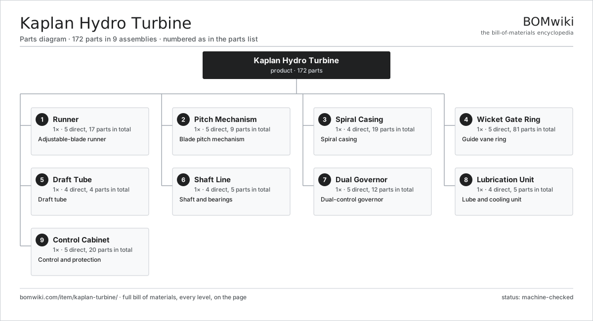
| # | Part | Qty | What it does |
|---|---|---|---|
| 1 | Runner 5 parts | 1× | Adjustable-blade runner |
| 2 | Pitch Mechanism 5 parts | 1× | Blade pitch mechanism |
| 3 | Spiral Casing 4 parts | 1× | Spiral casing |
| 4 | Wicket Gate Ring 5 parts | 1× | Guide vane ring |
| 5 | Draft Tube 4 parts | 1× | Draft tube |
| 6 | Shaft Line 4 parts | 1× | Shaft and bearings |
| 7 | Dual Governor 5 parts | 1× | Dual-control governor |
| 8 | Lubrication Unit 4 parts | 1× | Lube and cooling unit |
| 9 | Control Cabinet 5 parts | 1× | Control and protection |
3D model
No 3D model yet. Have a CAD file of this? Add a 3D model — STL renders right on this page; STEP, FreeCAD, and OpenSCAD sources are welcome too (openly licensed, like all 3D models on BOMwiki).
Build & assembly graph
expand / collapse · shared sub-assemblies converge · links to related products · est. labourTap an assembly to expand/collapse · tap a part to open it · use “Open page” for any node · drag to pan, scroll to zoom.
Bill of materials for Kaplan Hydro Turbine
9 top-level lines · 58 rows shown · 172 parts total · indented to 3 levels| # | Item / sub-assembly | Part no. | Qty/assy | Ext. qty | Parts | Type |
|---|---|---|---|---|---|---|
| 1 | Runner 5 parts | kaplan-turbine-runner | 1× | 1 | 17 | assembly |
| 1.1 | Runner Hub | kaplan-turbine-runner-hub | 1× | 1 | · | part |
| 1.2 | Runner Blade | kaplan-turbine-blade | 5× | 5 | · | part |
| 1.3 | Blade Trunnion | kaplan-turbine-trunnion | 5× | 5 | · | part |
| 1.4 | Blade Seal | kaplan-turbine-blade-seal | 5× | 5 | · | part |
| 1.5 | Discharge Ring | kaplan-turbine-discharge-ring | 1× | 1 | · | part |
| 2 | Pitch Mechanism 5 parts | kaplan-turbine-hub-servo | 1× | 1 | 9 | assembly |
| 2.1 | Hub Servo Piston | kaplan-turbine-servo-piston | 1× | 1 | · | part |
| 2.2 | Crosshead | kaplan-turbine-crosshead | 1× | 1 | · | part |
| 2.3 | Blade Link | kaplan-turbine-blade-link | 5× | 5 | · | part |
| 2.4 | Oil Head | kaplan-turbine-oil-head | 1× | 1 | · | part |
| 2.5 | Feedback Rod | kaplan-turbine-feedback-rod | 1× | 1 | · | part |
| 3 | Spiral Casing 4 parts | kaplan-turbine-spiral-case | 1× | 1 | 19 | assembly |
| 3.1 | Volute Shell | kaplan-turbine-volute-shell | 1× | 1 | · | part |
| 3.2 | Stay Ring | kaplan-turbine-stay-ring | 1× | 1 | · | part |
| 3.3 | Stay Vane | kaplan-turbine-stay-vane | 16× | 16 | · | part |
| 3.4 | Inlet Flange | kaplan-turbine-inlet-flange | 1× | 1 | · | part |
| 4 | Wicket Gate Ring 5 parts | kaplan-turbine-wicket-gates | 1× | 1 | 81 | assembly |
| 4.1 | Guide Vane | kaplan-turbine-guide-vane | 16× | 16 | · | part |
| 4.2 | Vane Lever | kaplan-turbine-vane-arm | 16× | 16 | · | part |
| 4.3 | Operating Ring | kaplan-turbine-shifting-ring | 1× | 1 | · | part |
| 4.4 | Vane Bushing | kaplan-turbine-vane-bushing | 32× | 32 | · | part |
| 4.5 | Shear Pin | kaplan-turbine-shear-pin | 16× | 16 | · | part |
| 5 | Draft Tube 4 parts | kaplan-turbine-draft-tube | 1× | 1 | 4 | assembly |
| 5.1 | Draft Cone | kaplan-turbine-draft-cone | 1× | 1 | · | part |
| 5.2 | Draft Elbow | kaplan-turbine-draft-elbow | 1× | 1 | · | part |
| 5.3 | Draft Pier | kaplan-turbine-draft-pier | 1× | 1 | · | part |
| 5.4 | Draft Liner | kaplan-turbine-draft-liner | 1× | 1 | · | part |
| 6 | Shaft Line 4 parts | kaplan-turbine-shaft-line | 1× | 1 | 5 | assembly |
| 6.1 | Main Shaft | kaplan-turbine-main-shaft | 1× | 1 | · | part |
| 6.2 | Guide Bearing | kaplan-turbine-guide-bearing | 1× | 1 | · | part |
| 6.3 | Coupling | kaplan-turbine-coupling | 1× | 1 | · | part |
| 6.4 | Oil Seal | oil-seal | 2× | 2 | · | part |
| 7 | Dual Governor 5 parts | kaplan-turbine-governor | 1× | 1 | 12 | assembly |
| 7.1 | Governor Pump | kaplan-turbine-gov-pump | 1× | 1 | · | part |
| 7.2 | Accumulator | kaplan-turbine-gov-accumulator | 1× | 1 | · | part |
| 7.3 | Gate Servomotor | kaplan-turbine-gate-servo | 2× | 2 | · | part |
| 7.4 | Speed Pickup | kaplan-turbine-speed-pickup | 1× | 1 | · | part |
| 7.5 | Dual Controller 4 parts | kaplan-turbine-gov-controller | 1× | 1 | 7 | assembly |
| 7.5.1 | Bare PCB | pcb-bare | 1× | 1 | · | part |
| 7.5.2 | Microcontroller | mcu | 1× | 1 | · | part |
| 7.5.3 | SMD Passive (R/C/L) | smd-passives | 1× | 1 | · | part |
| 7.5.4 | Connector | connector | 4× | 4 | · | part |
| 8 | Lubrication Unit 4 parts | kaplan-turbine-cooling | 1× | 1 | 5 | assembly |
| 8.1 | Lube Pump | kaplan-turbine-lube-pump | 1× | 1 | · | part |
| 8.2 | Oil Cooler | kaplan-turbine-oil-cooler | 1× | 1 | · | part |
| 8.3 | Oil Filter | kaplan-turbine-oil-filter | 2× | 2 | · | part |
| 8.4 | Oil Reservoir | kaplan-turbine-oil-tank | 1× | 1 | · | part |
| 9 | Control Cabinet 5 parts | kaplan-turbine-controls | 1× | 1 | 20 | assembly |
| 9.1 | Unit PLC 4 parts | kaplan-turbine-plc | 1× | 1 | 9 | assembly |
| 9.1.1 | Bare PCB | pcb-bare | 1× | 1 | · | part |
| 9.1.2 | Microcontroller | mcu | 1× | 1 | · | part |
| 9.1.3 | SMD Passive (R/C/L) | smd-passives | 1× | 1 | · | part |
| 9.1.4 | Connector | connector | 6× | 6 | · | part |
| 9.2 | Vibration Monitor | kaplan-turbine-vibration-monitor | 1× | 1 | · | part |
| 9.3 | Power Supply | power-supply | 1× | 1 | · | part |
| 9.4 | Relay | relay | 8× | 8 | · | part |
| 9.5 | Wire Bundle | wire-bundle | 1× | 1 | · | part |
Related products
same domain, ranked by shared parts Biomass Pellet Plant
404 parts · shares 2 with this page
Biomass Pellet Plant
404 parts · shares 2 with this page
 Concentrated Solar Power Receiver
855 parts · shares 2 with this page
Concentrated Solar Power Receiver
855 parts · shares 2 with this page
 Floating Offshore Wind Turbine
608 parts · shares 2 with this page
Green Hydrogen Electrolyzer Plant
2,171 parts · shares 2 with this page
Floating Offshore Wind Turbine
608 parts · shares 2 with this page
Green Hydrogen Electrolyzer Plant
2,171 parts · shares 2 with this page
 Pelton Hydro Turbine
111 parts · shares 2 with this page
Pelton Hydro Turbine
111 parts · shares 2 with this page
Sourcing: possible vendors
Prices, MOQ, and lead times are algorithmic estimates, not quotes, and not claims about these companies. Company mappings are curated by keyword; est. price band $100–$20M. How estimates work| Vendor | HQ | Specialty | MOQ | Lead time |
|---|---|---|---|---|
|
🇩🇰Vestas
vestas.com ↗
|
Aarhus, DK | Wind turbines | 500 units | 12–24 wks |
| firstsolar.com ↗ | Tempe, US | PV modules | 500 units | 12–24 wks |
|
🇨🇳LONGi
longi.com ↗
|
Xi'an, CN | Solar wafers & modules | 500 units | 12–24 wks |
| enphase.com ↗ | Fremont, US | Microinverters & storage | 500 units | 12–24 wks |
|
🇨🇳Sungrow
sungrowpower.com ↗
|
Hefei, CN | Solar inverters & storage | 500 units | 12–24 wks |
1,000-word article