Battery Energy Storage System
ProductOverview
A containerized battery energy storage system, or BESS, packages lithium battery racks, power electronics, cooling, and safety equipment inside a standard steel enclosure so a complete grid asset can be shipped, craned into place, and connected on site. A 20-foot container typically holds 3-5 MWh of usable energy and pairs with a power conversion system rated between roughly 1.5 and 3.4 MW, giving a 2-4 hour discharge duration that suits most grid applications. The cells are almost always lithium iron phosphate (LFP), chosen over higher-energy nickel chemistries because LFP tolerates abuse better, resists thermal runaway to higher temperatures, and reaches 6,000-10,000 full cycles before falling to 70-80% of its original capacity.
The system connects to the grid at a single AC point. On a charge command it draws AC power, rectifies it to DC, and pushes current into the battery; on a discharge command it inverts the stored DC energy back to grid-synchronized AC. Round-trip efficiency from AC to AC is usually 85-92%, with losses split between the power electronics, the cells, and parasitic loads such as cooling and controls. The Energy Management Controller coordinates every subsystem and presents one control interface to the operator, while the Battery Management System protects the cells underneath it.
How it works
Energy is stored chemically in the cells and moved in and out as DC current. Inside the Battery Rack, prismatic cells are welded in series to build a string voltage near 1,000 V, and several racks are wired in parallel onto a common DC bus that sits in the 1,000-1,500 V range. Higher bus voltage lowers current for a given power, which reduces conductor size and resistive loss.
The Power Conversion System is the bidirectional bridge between that DC bus and the AC grid. It uses an array of power semiconductor modules switched at high frequency to synthesize a three-phase waveform, then filters that waveform with line inductors before it reaches the AC Switchgear and Metering. The same hardware runs in reverse to charge, so the PCS is a four-quadrant converter that can also supply or absorb reactive power for voltage support. Most units operate grid-following, locking to the existing grid waveform, but grid-forming firmware lets the converter set voltage and frequency itself to support weak grids or to black-start.
Battery rack and cells
The cell is the atom of the system. A single Prismatic LFP Cell holds about 280 Ah at 3.2 V, roughly 0.9 kWh. Sixteen cells are clamped and welded into a module at around 52 V, and sixteen modules stack in a rack to reach the string voltage. With eight racks in a container, the assembly contains over two thousand cells, and a weak or shorted cell anywhere in a series string drags down the whole string. That is why cell-level monitoring is mandatory rather than optional.
Each module carries a monitor board that measures every cell voltage and several temperatures and performs passive balancing to keep cells within a few millivolts of each other. Series interconnects are handled by the Cell Busbar, laser-welded to keep contact resistance low and stable over thousands of cycles. The module data flows up to a rack controller, which sums the string and supervises the rack-level breaker and fuse.
Power conversion and the DC bus
Between the racks and the inverter sits the DC Bus and Combiner, a combiner that parallels the rack strings, fuses each one independently, and provides a main contactor and manual disconnect for isolation. Per-string fusing matters because a fault in one rack must not be fed by the stored energy of the other seven. A pre-charge circuit gently charges the inverter DC-link capacitors before the main contactors close, avoiding the inrush surge that would otherwise weld contacts or trip protection.
The PCS power stage runs hot, so it is liquid-cooled through a cold plate rather than relying on air alone. Its controller regulates current many thousands of times per second, holds the power factor commanded by the operator, and trips fast on DC overvoltage, AC fault, or loss of grid.
Thermal management and safety
Cell life and safety both depend on temperature, so the Thermal Management Skid skid circulates water-glycol coolant to cold plates under each rack and to the PCS, holding cells near 25 °C even when the container sits in desert heat. Keeping the pack within a narrow band slows calendar aging and prevents the local hot spots that can seed a runaway. A chiller rejects the heat to ambient, redundant pumps move the coolant, and a controller modulates flow against the measured loop temperature and pressure.
Safety is layered because a lithium cell that enters thermal runaway vents flammable gas before it ignites. The Fire Detection and Suppression system uses aspirating smoke detection and hydrogen sensing to catch off-gassing early, often before any flame, and can shut down charging and start exhaust ventilation to keep gas below its explosive limit. If ignition occurs, clean-agent or aerosol cylinders discharge through fixed nozzles. The Battery Management System adds the electrical layer: it estimates state of charge and state of health, enforces per-cell voltage and temperature limits, and opens contactors before any cell is driven outside its safe window. These measures map directly to the testing and spacing rules in UL 9540A and NFPA 855.
Controls and grid services
What makes the container useful to a grid operator is the Energy Management Controller. It dispatches charge and discharge against a schedule or a real-time signal, respects the limits the BMS reports, and exposes the whole system over SCADA protocols such as Modbus, DNP3, or IEC 61850. Through the AC Switchgear and Metering and its protection relay the system can provide frequency regulation, where it charges and discharges in seconds to hold grid frequency, peak shaving, where it discharges during expensive demand peaks, energy arbitrage between cheap and expensive hours, and backup or black-start support during outages. A single 2-4 hour container rarely runs alone; sites commonly array dozens of them behind shared transformers to build storage plants of tens or hundreds of megawatt-hours, and the EMS in each unit answers to a plant-level controller above it.
Battery Energy Storage System parts and their functions
9 top-level parts · 17,429 parts in total · full bill of materials below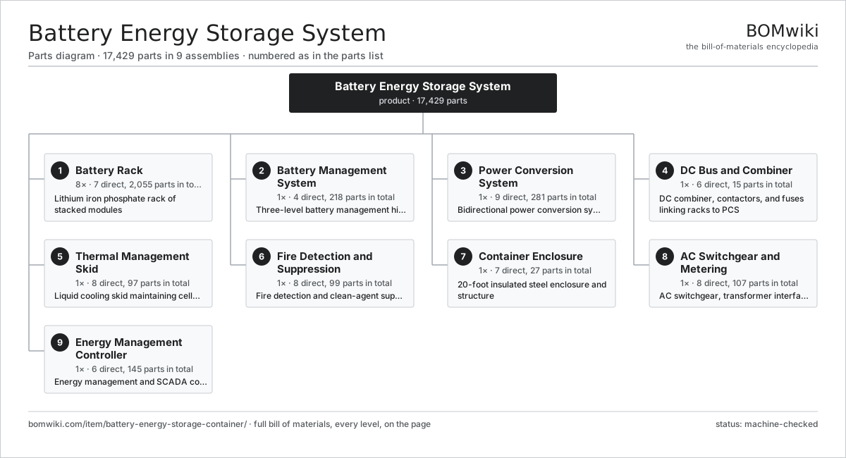
| # | Part | Qty | What it does |
|---|---|---|---|
| 1 | Battery Rack 7 parts | 8× | Lithium iron phosphate rack of stacked modules |
| 2 | Battery Management System 4 parts | 1× | Three-level battery management hierarchy |
| 3 | Power Conversion System 9 parts | 1× | Bidirectional power conversion system (inverter) |
| 4 | DC Bus and Combiner 6 parts | 1× | DC combiner, contactors, and fuses linking racks to PCS |
| 5 | Thermal Management Skid 8 parts | 1× | Liquid cooling skid maintaining cell temperature |
| 6 | Fire Detection and Suppression 8 parts | 1× | Fire detection and clean-agent suppression |
| 7 | Container Enclosure 7 parts | 1× | 20-foot insulated steel enclosure and structure |
| 8 | AC Switchgear and Metering 8 parts | 1× | AC switchgear, transformer interface, and metering |
| 9 | Energy Management Controller 6 parts | 1× | Energy management and SCADA controller with comms |
3D model
No 3D model yet. Have a CAD file of this? Add a 3D model — STL renders right on this page; STEP, FreeCAD, and OpenSCAD sources are welcome too (openly licensed, like all 3D models on BOMwiki).
Build & assembly graph
expand / collapse · shared sub-assemblies converge · links to related products · est. labourTap an assembly to expand/collapse · tap a part to open it · use “Open page” for any node · drag to pan, scroll to zoom.
Bill of materials for Battery Energy Storage System
9 top-level lines · 115 rows shown · 17,429 parts total · indented to 3 levels| # | Item / sub-assembly | Part no. | Qty/assy | Ext. qty | Parts | Type |
|---|---|---|---|---|---|---|
| 1 | Battery Rack 7 parts | battery-energy-storage-container-battery-rack | 8× | 8 | 2,055 | assembly |
| 1.1 | LFP Battery Module 6 parts | battery-energy-storage-container-module | 16× | 128 | 120 | assembly |
| 1.1.1 | Prismatic LFP Cell | battery-energy-storage-container-cell | 16× | 2,048 | · | part |
| 1.1.2 | Cell Busbar | battery-energy-storage-container-cell-busbar | 15× | 1,920 | · | part |
| 1.1.3 | Module Monitor Board 5 parts + deeper › | battery-energy-storage-container-module-bmb | 1× | 128 | 85 | assembly |
| 1.1.4 | Module Housing | battery-energy-storage-container-module-case | 1× | 128 | · | part |
| 1.1.5 | Module Terminal | battery-energy-storage-container-module-terminal | 2× | 256 | · | part |
| 1.1.6 | Fastener Set | fastener-set | 1× | 128 | · | part |
| 1.2 | Rack BMS Controller 6 parts | battery-energy-storage-container-rack-bmu | 1× | 8 | 129 | assembly |
| 1.2.1 | Bare PCB | pcb-bare | 1× | 8 | · | part |
| 1.2.2 | Microcontroller | mcu | 1× | 8 | · | part |
| 1.2.3 | String Current Sensor | battery-energy-storage-container-current-shunt | 1× | 8 | · | part |
| 1.2.4 | Isolated CAN Transceiver | battery-energy-storage-container-can-iso | 2× | 16 | · | part |
| 1.2.5 | SMD Passive (R/C/L) | smd-passives | 120× | 960 | · | part |
| 1.2.6 | Connector | connector | 4× | 32 | · | part |
| 1.3 | Rack Busbar | battery-energy-storage-container-rack-busbar | 2× | 16 | · | part |
| 1.4 | DC String Breaker | battery-energy-storage-container-rack-breaker | 1× | 8 | · | part |
| 1.5 | String Fuse | battery-energy-storage-container-rack-fuse | 1× | 8 | · | part |
| 1.6 | Rack Frame | battery-energy-storage-container-rack-frame | 1× | 8 | · | part |
| 1.7 | Wire Bundle | wire-bundle | 1× | 8 | · | part |
| 2 | Battery Management System 4 parts | battery-energy-storage-container-bms | 1× | 1 | 218 | assembly |
| 2.1 | System BMS Master 5 parts | battery-energy-storage-container-bms-master | 1× | 1 | 215 | assembly |
| 2.1.1 | Bare PCB | pcb-bare | 1× | 1 | · | part |
| 2.1.2 | Microcontroller | mcu | 2× | 2 | · | part |
| 2.1.3 | Isolated CAN Transceiver | battery-energy-storage-container-can-iso | 4× | 4 | · | part |
| 2.1.4 | SMD Passive (R/C/L) | smd-passives | 200× | 200 | · | part |
| 2.1.5 | Connector | connector | 8× | 8 | · | part |
| 2.2 | BMS Power Supply | battery-energy-storage-container-bms-psu | 1× | 1 | · | part |
| 2.3 | Insulation Monitor | battery-energy-storage-container-iso-monitor | 1× | 1 | · | part |
| 2.4 | Wire Bundle | wire-bundle | 1× | 1 | · | part |
| 3 | Power Conversion System 9 parts | battery-energy-storage-container-pcs | 1× | 1 | 281 | assembly |
| 3.1 | Power Semiconductor Module | battery-energy-storage-container-igbt | 6× | 6 | · | part |
| 3.2 | Gate Driver Board 3 parts | battery-energy-storage-container-gate-driver | 1× | 1 | 107 | assembly |
| 3.2.1 | Bare PCB | pcb-bare | 1× | 1 | · | part |
| 3.2.2 | Gate Driver IC | battery-energy-storage-container-gate-ic | 6× | 6 | · | part |
| 3.2.3 | SMD Passive (R/C/L) | smd-passives | 100× | 100 | · | part |
| 3.3 | DC-Link Capacitor | battery-energy-storage-container-dc-cap | 6× | 6 | · | part |
| 3.4 | AC Filter Inductor | battery-energy-storage-container-ac-inductor | 3× | 3 | · | part |
| 3.5 | PCS Control Board 4 parts | battery-energy-storage-container-pcs-control | 1× | 1 | 154 | assembly |
| 3.5.1 | Bare PCB | pcb-bare | 1× | 1 | · | part |
| 3.5.2 | Microcontroller | mcu | 1× | 1 | · | part |
| 3.5.3 | Isolated CAN Transceiver | battery-energy-storage-container-can-iso | 2× | 2 | · | part |
| 3.5.4 | SMD Passive (R/C/L) | smd-passives | 150× | 150 | · | part |
| 3.6 | Pre-charge Circuit | battery-energy-storage-container-pcs-precharge | 1× | 1 | · | part |
| 3.7 | PCS Cold Plate | battery-energy-storage-container-pcs-cooling | 1× | 1 | · | part |
| 3.8 | PCS Cabinet | battery-energy-storage-container-pcs-cabinet | 1× | 1 | · | part |
| 3.9 | Main Contactor | battery-energy-storage-container-pcs-contactor | 2× | 2 | · | part |
| 4 | DC Bus and Combiner 6 parts | battery-energy-storage-container-dc-bus | 1× | 1 | 15 | assembly |
| 4.1 | Combiner Busbar | battery-energy-storage-container-dc-combiner-busbar | 2× | 2 | · | part |
| 4.2 | DC String Fuse | battery-energy-storage-container-dc-string-fuse | 8× | 8 | · | part |
| 4.3 | DC Bus Contactor | battery-energy-storage-container-dc-main-contactor | 2× | 2 | · | part |
| 4.4 | DC Surge Protector | battery-energy-storage-container-dc-spd | 1× | 1 | · | part |
| 4.5 | DC Disconnect Switch | battery-energy-storage-container-dc-disconnect | 1× | 1 | · | part |
| 4.6 | Wire Bundle | wire-bundle | 1× | 1 | · | part |
| 5 | Thermal Management Skid 8 parts | battery-energy-storage-container-thermal | 1× | 1 | 97 | assembly |
| 5.1 | Coolant Chiller | battery-energy-storage-container-chiller | 1× | 1 | · | part |
| 5.2 | Coolant Pump | battery-energy-storage-container-coolant-pump | 2× | 2 | · | part |
| 5.3 | Rack Cold Plate | battery-energy-storage-container-cold-plate | 8× | 8 | · | part |
| 5.4 | Coolant Manifold | battery-energy-storage-container-coolant-manifold | 1× | 1 | · | part |
| 5.5 | Coolant Hose | battery-energy-storage-container-coolant-hose | 16× | 16 | · | part |
| 5.6 | Expansion Tank | battery-energy-storage-container-expansion-tank | 1× | 1 | · | part |
| 5.7 | Pressure Sensor | pressure-sensor | 2× | 2 | · | part |
| 5.8 | Thermal Controller 4 parts | battery-energy-storage-container-thermal-control | 1× | 1 | 66 | assembly |
| 5.8.1 | Bare PCB | pcb-bare | 1× | 1 | · | part |
| 5.8.2 | Microcontroller | mcu | 1× | 1 | · | part |
| 5.8.3 | Relay | relay | 4× | 4 | · | part |
| 5.8.4 | SMD Passive (R/C/L) | smd-passives | 60× | 60 | · | part |
| 6 | Fire Detection and Suppression 8 parts | battery-energy-storage-container-fire | 1× | 1 | 99 | assembly |
| 6.1 | Fire Alarm Panel 4 parts | battery-energy-storage-container-fire-panel | 1× | 1 | 78 | assembly |
| 6.1.1 | Bare PCB | pcb-bare | 1× | 1 | · | part |
| 6.1.2 | Microcontroller | mcu | 1× | 1 | · | part |
| 6.1.3 | Relay | relay | 6× | 6 | · | part |
| 6.1.4 | SMD Passive (R/C/L) | smd-passives | 70× | 70 | · | part |
| 6.2 | Aspirating Smoke Detector | battery-energy-storage-container-smoke-detector | 4× | 4 | · | part |
| 6.3 | Hydrogen Detector | battery-energy-storage-container-h2-detector | 2× | 2 | · | part |
| 6.4 | Heat Detector | battery-energy-storage-container-heat-detector | 4× | 4 | · | part |
| 6.5 | Suppression Agent Cylinder | battery-energy-storage-container-suppression-cylinder | 2× | 2 | · | part |
| 6.6 | Suppression Nozzle | battery-energy-storage-container-suppression-nozzle | 6× | 6 | · | part |
| 6.7 | Exhaust Fan | battery-energy-storage-container-exhaust-fan | 1× | 1 | · | part |
| 6.8 | Fire Damper | battery-energy-storage-container-fire-damper | 2× | 2 | · | part |
| 7 | Container Enclosure 7 parts | battery-energy-storage-container-enclosure | 1× | 1 | 27 | assembly |
| 7.1 | Container Frame | battery-energy-storage-container-frame | 1× | 1 | · | part |
| 7.2 | Insulated Wall Panel | battery-energy-storage-container-wall-panel | 8× | 8 | · | part |
| 7.3 | Sheet Metal Panel | sheet-panel | 6× | 6 | · | part |
| 7.4 | Access Door | battery-energy-storage-container-door | 2× | 2 | · | part |
| 7.5 | Structural Floor | battery-energy-storage-container-floor | 1× | 1 | · | part |
| 7.6 | Cable Gland | battery-energy-storage-container-cable-gland | 8× | 8 | · | part |
| 7.7 | Fastener Set | fastener-set | 1× | 1 | · | part |
| 8 | AC Switchgear and Metering 8 parts | battery-energy-storage-container-switchgear | 1× | 1 | 107 | assembly |
| 8.1 | AC Circuit Breaker | battery-energy-storage-container-ac-breaker | 1× | 1 | · | part |
| 8.2 | AC Busbar | battery-energy-storage-container-ac-busbar | 1× | 1 | · | part |
| 8.3 | Grid Protection Relay 4 parts | battery-energy-storage-container-protection-relay | 1× | 1 | 96 | assembly |
| 8.3.1 | Bare PCB | pcb-bare | 1× | 1 | · | part |
| 8.3.2 | Microcontroller | mcu | 1× | 1 | · | part |
| 8.3.3 | Relay | relay | 4× | 4 | · | part |
| 8.3.4 | SMD Passive (R/C/L) | smd-passives | 90× | 90 | · | part |
| 8.4 | Power Meter | battery-energy-storage-container-meter | 1× | 1 | · | part |
| 8.5 | Current Transformer | battery-energy-storage-container-ct | 3× | 3 | · | part |
| 8.6 | Voltage Transformer | battery-energy-storage-container-vt | 3× | 3 | · | part |
| 8.7 | Transformer Interface | battery-energy-storage-container-transformer-interface | 1× | 1 | · | part |
| 8.8 | Auxiliary Power Supply | battery-energy-storage-container-aux-supply | 1× | 1 | · | part |
| 9 | Energy Management Controller 6 parts | battery-energy-storage-container-ems | 1× | 1 | 145 | assembly |
| 9.1 | EMS Controller 4 parts | battery-energy-storage-container-ems-controller | 1× | 1 | 138 | assembly |
| 9.1.1 | Bare PCB | pcb-bare | 1× | 1 | · | part |
| 9.1.2 | Microcontroller | mcu | 1× | 1 | · | part |
| 9.1.3 | SMD Passive (R/C/L) | smd-passives | 130× | 130 | · | part |
| 9.1.4 | Connector | connector | 6× | 6 | · | part |
| 9.2 | Industrial Ethernet Switch | battery-energy-storage-container-network-switch | 1× | 1 | · | part |
| 9.3 | Communications Gateway | battery-energy-storage-container-comms-gateway | 1× | 1 | · | part |
| 9.4 | Operator HMI 3 parts | battery-energy-storage-container-hmi | 1× | 1 | 3 | assembly |
| 9.4.1 | LCD Panel | lcd-panel | 1× | 1 | · | part |
| 9.4.2 | Bare PCB | pcb-bare | 1× | 1 | · | part |
| 9.4.3 | Microcontroller | mcu | 1× | 1 | · | part |
| 9.5 | Control UPS | battery-energy-storage-container-ups | 1× | 1 | · | part |
| 9.6 | Power Supply | power-supply | 1× | 1 | · | part |
Related products
same domain, ranked by shared parts PEM Hydrogen Electrolyzer
305 parts · shares 4 with this page
Utility-Scale Solar Inverter
204 parts · shares 4 with this page
PEM Hydrogen Electrolyzer
305 parts · shares 4 with this page
Utility-Scale Solar Inverter
204 parts · shares 4 with this page
 Wind Turbine
28,312 parts · shares 4 with this page
Wind Turbine
28,312 parts · shares 4 with this page
 Wind Turbine Nacelle
287 parts · shares 4 with this page
Wind Turbine Nacelle
287 parts · shares 4 with this page
Sourcing: possible vendors
Prices, MOQ, and lead times are algorithmic estimates, not quotes, and not claims about these companies. Company mappings are curated by keyword; est. price band $100–$20M. How estimates work| Vendor | HQ | Specialty | MOQ | Lead time |
|---|---|---|---|---|
|
🇩🇰Vestas
vestas.com ↗
|
Aarhus, DK | Wind turbines | 500 units | 12–24 wks |
| firstsolar.com ↗ | Tempe, US | PV modules | 500 units | 12–24 wks |
|
🇨🇳LONGi
longi.com ↗
|
Xi'an, CN | Solar wafers & modules | 500 units | 12–24 wks |
| enphase.com ↗ | Fremont, US | Microinverters & storage | 500 units | 12–24 wks |
|
🇨🇳Sungrow
sungrowpower.com ↗
|
Hefei, CN | Solar inverters & storage | 500 units | 12–24 wks |
1,087-word article