Floating Offshore Wind Turbine
ProductOverview
A floating offshore wind turbine puts a conventional multi-megawatt turbine on a buoyant, moored platform instead of a fixed foundation driven into the seabed. This opens deep-water sites (beyond roughly 60 m, where monopiles and jackets become uneconomic) where winds are stronger and steadier and where the turbine sits far enough from shore to avoid most visual and acoustic objections. The machine is the same family of equipment used onshore and in fixed-bottom offshore wind, but every subsystem is sized and protected for a structure that pitches, rolls and heaves with the sea.
The product breaks into seven major subsystems: the nacelle holding the drivetrain, the rotor that captures the wind, the tower that raises it, the floating platform that provides buoyancy and stability, the mooring system that holds station, the power export system that conditions and delivers the electricity, and the control system that ties it all together.
Rotor and Nacelle
The rotor is a three-blade upwind design 150–230 m in diameter. Each rotor blade is a hollow composite structure up to 115 m long, built from two spar caps of unidirectional carbon or glass laminate that carry the flapwise bending load, joined by shear webs and wrapped in an aerodynamic blade shell. Embedded lightning receptors route strike current to ground. The blades bolt to a cast hub through individual pitch systems, each with a pitch bearing and a backup battery that feathers the blade to safety if grid power is lost.
Inside the nacelle, the rotor turns a forged main shaft on two main bearings. A three-stage gearbox, built around a planetary first stage and helical gear pairs, steps the 6–12 rpm rotor speed up to generator speed. The generator is a doubly-fed or permanent-magnet machine rated 6–15 MW. Four yaw drives rotate the nacelle on a yaw bearing to face the wind. The whole drivetrain mounts on a cast bedplate under a GFRP cover, with a cooling system dumping gearbox and generator heat to a marine radiator.
Floating Platform
The floating platform is the part that distinguishes this machine. Three common hull types are used: a deep slender spar, a wide semi-submersible with multiple columns, and a shallow barge. The semi-submersible shown here uses three buoyancy columns tied together by submerged pontoons into a stiff triangle. A ballast system combines fixed heavy ballast with active seawater pumped between tanks by ballast pumps through ballast valves, holding the platform level as the rotor thrust shifts with wind direction. The tower base meets the hull at a welded transition deck. A bilge system with ingress sensors guards each watertight compartment against flooding.
Platform stability comes from a balance of waterplane area, ballast and mooring stiffness. The control system actively damps tower motion so that platform pitch does not pump energy back into the rotor, a coupling that, left alone, can drive unstable oscillations.
Mooring and Station-Keeping
The mooring system holds the platform within a watch circle of tens of metres. Three to six mooring lines, each a composite of studless chain and synthetic polyester rope 500–1500 m long, run from hull fairleads down to seabed anchors. Catenary moorings rely on the weight of the chain; taut moorings use the elasticity of polyester rope for a smaller footprint. Each line carries a tension sensor so the control room sees a line failure immediately. Anchors are drag-embedment plates for soft seabeds or suction buckets where chain dragging is unacceptable.
Tower
The tower is a conical tube of welded S355 steel built from several tower sections 4–6 m in diameter, joined at bolted tower flanges. Internal platforms and a ladder give access from the deck to the nacelle. A multi-layer coating system (zinc, epoxy, polyurethane) gives the C5-M corrosion protection that the salt-laden marine atmosphere demands. Floating towers run slightly softer than fixed-bottom towers to keep their natural frequency clear of the platform motion frequencies.
Power Export and Control
Generator output is conditioned by the power export system. A full or partial power converter, built from IGBT modules and DC-link capacitors, decouples variable rotor speed from grid frequency. A step-up transformer raises voltage to the 33–66 kV collection level, MV switchgear protects the feeder, and a dynamic export cable carries the power down a lazy-wave shape to the seabed array cable. The suspended cable must tolerate continuous bending as the platform moves, so it carries buoyancy modules that hold its shape.
The control system adds a layer absent from onshore turbines. Alongside the main controller, an anemometer and a condition monitor, a motion reference unit measures platform pitch, roll and heave. The controller uses this to add motion damping to the pitch demand, trading a little energy capture for far lower fatigue loads. A UPS keeps the controls and the blade-feathering function alive through grid faults, so the rotor can always be brought to a safe idle.
Operation and Use
Floating turbines are assembled and commissioned quayside, then towed to site and connected, which avoids the heavy-lift jack-up vessels that fixed-bottom installation needs. Major component swaps can, in principle, be done by towing the unit back to port. Sites suit deep-water regions off Japan, the US West Coast, the Mediterranean and the northern North Sea, where the seabed drops away too quickly for fixed foundations. The design trades higher steel and mooring cost against access to a far larger resource of strong, consistent deep-water wind.
Floating Offshore Wind Turbine parts and their functions
7 top-level parts · 608 parts in total · full bill of materials below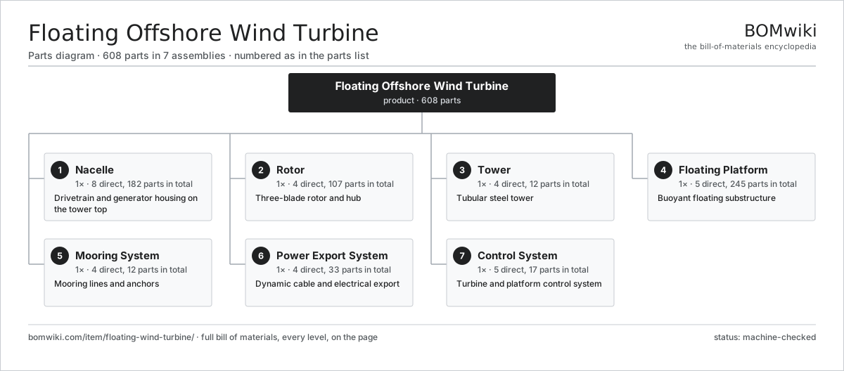
| # | Part | Qty | What it does |
|---|---|---|---|
| 1 | Nacelle 8 parts | 1× | Drivetrain and generator housing on the tower top |
| 2 | Rotor 4 parts | 1× | Three-blade rotor and hub |
| 3 | Tower 4 parts | 1× | Tubular steel tower |
| 4 | Floating Platform 5 parts | 1× | Buoyant floating substructure |
| 5 | Mooring System 4 parts | 1× | Mooring lines and anchors |
| 6 | Power Export System 4 parts | 1× | Dynamic cable and electrical export |
| 7 | Control System 5 parts | 1× | Turbine and platform control system |
3D model
No 3D model yet. Have a CAD file of this? Add a 3D model — STL renders right on this page; STEP, FreeCAD, and OpenSCAD sources are welcome too (openly licensed, like all 3D models on BOMwiki).
Build & assembly graph
expand / collapse · shared sub-assemblies converge · links to related products · est. labourTap an assembly to expand/collapse · tap a part to open it · use “Open page” for any node · drag to pan, scroll to zoom.
Bill of materials for Floating Offshore Wind Turbine
7 top-level lines · 92 rows shown · 608 parts total · indented to 3 levels| # | Item / sub-assembly | Part no. | Qty/assy | Ext. qty | Parts | Type |
|---|---|---|---|---|---|---|
| 1 | Nacelle 8 parts | floating-wind-turbine-nacelle | 1× | 1 | 182 | assembly |
| 1.1 | Main Shaft | floating-wind-turbine-main-shaft | 1× | 1 | · | part |
| 1.2 | Main Bearing 2 parts | floating-wind-turbine-main-bearing | 2× | 2 | · | part |
| 1.2.1 | Ball Bearing | ball-bearing | 1× | 2 | · | part |
| 1.2.2 | Oil Seal | oil-seal | 2× | 4 | · | part |
| 1.3 | Gearbox 5 parts | floating-wind-turbine-gearbox | 1× | 1 | 14 | assembly |
| 1.3.1 | Planetary Stage | floating-wind-turbine-planet-stage | 1× | 1 | · | part |
| 1.3.2 | Helical Gear Pair | gear-pair | 2× | 2 | · | part |
| 1.3.3 | Gearbox Housing | gearbox-housing | 1× | 1 | · | part |
| 1.3.4 | Ball Bearing | ball-bearing | 6× | 6 | · | part |
| 1.3.5 | Oil Seal | oil-seal | 4× | 4 | · | part |
| 1.4 | Generator 4 parts | floating-wind-turbine-generator | 1× | 1 | 25 | assembly |
| 1.4.1 | Stator Assembly 3 parts + deeper › | stator-assembly | 1× | 1 | 3 | assembly |
| 1.4.2 | Rotor Assembly 4 parts + deeper › | rotor-assembly | 1× | 1 | 19 | assembly |
| 1.4.3 | Slip Ring Unit | floating-wind-turbine-slip-ring | 1× | 1 | · | part |
| 1.4.4 | Ball Bearing | ball-bearing | 2× | 2 | · | part |
| 1.5 | Yaw Drive 3 parts | floating-wind-turbine-yaw-drive | 4× | 4 | 26 | assembly |
| 1.5.1 | Servo Motor 4 parts + deeper › | servo-motor | 1× | 4 | 24 | assembly |
| 1.5.2 | Helical Gear Pair | gear-pair | 1× | 4 | · | part |
| 1.5.3 | Yaw Bearing 1 parts + deeper › | floating-wind-turbine-yaw-bearing | 1× | 4 | · | part |
| 1.6 | Bedplate | floating-wind-turbine-bedplate | 1× | 1 | · | part |
| 1.7 | Nacelle Cover 1 parts | floating-wind-turbine-nacelle-cover | 1× | 1 | · | part |
| 1.7.1 | Sheet Metal Panel | sheet-panel | 4× | 4 | · | part |
| 1.8 | Cooling System 3 parts | floating-wind-turbine-cooling | 1× | 1 | 27 | assembly |
| 1.8.1 | Radiator | floating-wind-turbine-radiator | 1× | 1 | · | part |
| 1.8.2 | Servo Motor 4 parts + deeper › | servo-motor | 1× | 1 | 24 | assembly |
| 1.8.3 | Pressure Sensor | pressure-sensor | 2× | 2 | · | part |
| 2 | Rotor 4 parts | floating-wind-turbine-rotor | 1× | 1 | 107 | assembly |
| 2.1 | Rotor Blade 4 parts | floating-wind-turbine-blade | 3× | 3 | 9 | assembly |
| 2.1.1 | Spar Cap | floating-wind-turbine-spar-cap | 2× | 6 | · | part |
| 2.1.2 | Shear Web | floating-wind-turbine-shear-web | 2× | 6 | · | part |
| 2.1.3 | Blade Shell | floating-wind-turbine-blade-shell | 2× | 6 | · | part |
| 2.1.4 | Lightning Receptor | floating-wind-turbine-lightning-receptor | 3× | 9 | · | part |
| 2.2 | Rotor Hub | floating-wind-turbine-hub | 1× | 1 | · | part |
| 2.3 | Pitch System 3 parts | floating-wind-turbine-pitch-system | 3× | 3 | 26 | assembly |
| 2.3.1 | Servo Motor 4 parts + deeper › | servo-motor | 1× | 3 | 24 | assembly |
| 2.3.2 | Pitch Bearing 1 parts + deeper › | floating-wind-turbine-pitch-bearing | 1× | 3 | · | part |
| 2.3.3 | Pitch Backup Battery | floating-wind-turbine-pitch-battery | 1× | 3 | · | part |
| 2.4 | Spinner | floating-wind-turbine-spinner | 1× | 1 | · | part |
| 3 | Tower 4 parts | floating-wind-turbine-tower | 1× | 1 | 12 | assembly |
| 3.1 | Tower Section 1 parts | floating-wind-turbine-tower-section | 3× | 3 | · | part |
| 3.1.1 | Sheet Metal Panel | sheet-panel | 1× | 3 | · | part |
| 3.2 | Tower Flange 1 parts | floating-wind-turbine-tower-flange | 4× | 4 | · | part |
| 3.2.1 | Fastener Set | fastener-set | 1× | 4 | · | part |
| 3.3 | Internal Platform | floating-wind-turbine-internal-platform | 4× | 4 | · | part |
| 3.4 | Tower Coating | floating-wind-turbine-tower-coating | 1× | 1 | · | part |
| 4 | Floating Platform 5 parts | floating-wind-turbine-platform | 1× | 1 | 245 | assembly |
| 4.1 | Buoyancy Column | floating-wind-turbine-column | 3× | 3 | · | part |
| 4.2 | Pontoon | floating-wind-turbine-pontoon | 3× | 3 | · | part |
| 4.3 | Ballast System 3 parts | floating-wind-turbine-ballast | 1× | 1 | 200 | assembly |
| 4.3.1 | Ballast Pump 2 parts + deeper › | floating-wind-turbine-ballast-pump | 2× | 2 | · | part |
| 4.3.2 | Ballast Valve 1 parts + deeper › | floating-wind-turbine-ballast-valve | 6× | 6 | · | part |
| 4.3.3 | Pressure Sensor | pressure-sensor | 4× | 4 | · | part |
| 4.4 | Transition Deck 2 parts | floating-wind-turbine-deck | 1× | 1 | · | part |
| 4.4.1 | Sheet Metal Panel | sheet-panel | 2× | 2 | · | part |
| 4.4.2 | Fastener Set | fastener-set | 1× | 1 | · | part |
| 4.5 | Bilge System 3 parts | floating-wind-turbine-bilge-system | 1× | 1 | 36 | assembly |
| 4.5.1 | Ballast Pump 2 parts + deeper › | floating-wind-turbine-ballast-pump | 1× | 1 | · | part |
| 4.5.2 | Pressure Sensor | pressure-sensor | 4× | 4 | · | part |
| 4.5.3 | Water Ingress Sensor | floating-wind-turbine-water-sensor | 6× | 6 | · | part |
| 5 | Mooring System 4 parts | floating-wind-turbine-mooring | 1× | 1 | 12 | assembly |
| 5.1 | Mooring Line | floating-wind-turbine-mooring-line | 3× | 3 | · | part |
| 5.2 | Anchor | floating-wind-turbine-anchor | 3× | 3 | · | part |
| 5.3 | Fairlead | floating-wind-turbine-fairlead | 3× | 3 | · | part |
| 5.4 | Line Tension Sensor 1 parts | floating-wind-turbine-tensioner | 3× | 3 | · | part |
| 5.4.1 | Pressure Sensor | pressure-sensor | 1× | 3 | · | part |
| 6 | Power Export System 4 parts | floating-wind-turbine-power-export | 1× | 1 | 33 | assembly |
| 6.1 | Power Converter 4 parts | floating-wind-turbine-converter | 1× | 1 | 19 | assembly |
| 6.1.1 | IGBT Module | floating-wind-turbine-igbt-module | 6× | 6 | · | part |
| 6.1.2 | Bare PCB | pcb-bare | 4× | 4 | · | part |
| 6.1.3 | DC-Link Capacitor | floating-wind-turbine-dc-capacitor | 8× | 8 | · | part |
| 6.1.4 | Radiator | floating-wind-turbine-radiator | 1× | 1 | · | part |
| 6.2 | Step-Up Transformer 1 parts | floating-wind-turbine-transformer | 1× | 1 | · | part |
| 6.2.1 | Stator Assembly 3 parts + deeper › | stator-assembly | 1× | 1 | 3 | assembly |
| 6.3 | MV Switchgear 2 parts | floating-wind-turbine-switchgear | 1× | 1 | · | part |
| 6.3.1 | Relay | relay | 4× | 4 | · | part |
| 6.3.2 | Connector | connector | 6× | 6 | · | part |
| 6.4 | Dynamic Export Cable 1 parts | floating-wind-turbine-dynamic-cable | 1× | 1 | · | part |
| 6.4.1 | Wire Bundle | wire-bundle | 1× | 1 | · | part |
| 7 | Control System 5 parts | floating-wind-turbine-control | 1× | 1 | 17 | assembly |
| 7.1 | Main Controller 4 parts | floating-wind-turbine-main-controller | 1× | 1 | 9 | assembly |
| 7.1.1 | Microcontroller | mcu | 2× | 2 | · | part |
| 7.1.2 | Bare PCB | pcb-bare | 2× | 2 | · | part |
| 7.1.3 | SMD Passive (R/C/L) | smd-passives | 1× | 1 | · | part |
| 7.1.4 | Relay | relay | 4× | 4 | · | part |
| 7.2 | Motion Reference Unit | floating-wind-turbine-mru | 1× | 1 | · | part |
| 7.3 | Anemometer | floating-wind-turbine-anemometer | 1× | 1 | · | part |
| 7.4 | Condition Monitor 2 parts | floating-wind-turbine-condition-monitor | 1× | 1 | · | part |
| 7.4.1 | Pressure Sensor | pressure-sensor | 4× | 4 | · | part |
| 7.4.2 | Bare PCB | pcb-bare | 1× | 1 | · | part |
| 7.5 | UPS 1 parts | floating-wind-turbine-ups | 1× | 1 | · | part |
| 7.5.1 | Power Supply | power-supply | 1× | 1 | · | part |
Related products
same domain, ranked by shared parts Wind Turbine
28,312 parts · shares 18 with this page
Wind Turbine
28,312 parts · shares 18 with this page
 Wind Turbine Nacelle
287 parts · shares 18 with this page
Wind Turbine Nacelle
287 parts · shares 18 with this page
 Biomass Pellet Plant
404 parts · shares 17 with this page
Biomass Pellet Plant
404 parts · shares 17 with this page
 Concentrated Solar Power Receiver
855 parts · shares 17 with this page
Green Hydrogen Electrolyzer Plant
2,171 parts · shares 16 with this page
Utility-Scale Solar Inverter
204 parts · shares 16 with this page
Concentrated Solar Power Receiver
855 parts · shares 17 with this page
Green Hydrogen Electrolyzer Plant
2,171 parts · shares 16 with this page
Utility-Scale Solar Inverter
204 parts · shares 16 with this page
Sourcing: possible vendors
Prices, MOQ, and lead times are algorithmic estimates, not quotes, and not claims about these companies. Company mappings are curated by keyword; est. price band $100–$20M. How estimates work| Vendor | HQ | Specialty | MOQ | Lead time |
|---|---|---|---|---|
|
🇩🇰Vestas
vestas.com ↗
|
Aarhus, DK | Wind turbines | 500 units | 12–24 wks |
| firstsolar.com ↗ | Tempe, US | PV modules | 500 units | 12–24 wks |
|
🇨🇳LONGi
longi.com ↗
|
Xi'an, CN | Solar wafers & modules | 500 units | 12–24 wks |
| enphase.com ↗ | Fremont, US | Microinverters & storage | 500 units | 12–24 wks |
|
🇨🇳Sungrow
sungrowpower.com ↗
|
Hefei, CN | Solar inverters & storage | 500 units | 12–24 wks |
1,199-word article