Hydropower Penstock
ProductOverview
A penstock is the pressure pipe that carries water from a reservoir or forebay down to a hydropower turbine. It converts the static head of the stored water into the high-pressure flow that drives the runner. Penstocks range from short steel pipes a few metres long at low-head run-of-river plants to inclined conduits several kilometres long at high-head mountain schemes. The diameter is set by the design flow and an economic balance between head loss and steel cost: larger pipe loses less energy to friction but costs more, so most penstocks run at flow velocities of 3 to 7 m/s.
The conduit is fabricated from rolled and welded steel sections called cans. Each Shell Can is a plate rolled into a cylinder, closed by a Longitudinal Seam Weld, then joined to the next can by a Girth Weld. Wall thickness increases from the intake to the powerhouse because internal pressure rises with the static head: a penstock under 600 m of head sees about 6 MPa at the bottom, so the lower cans may be 50 mm thick or more while the upper cans are under 15 mm.
How it works and hydraulics
The energy available is the product of head and flow. Gross head is the elevation difference between the reservoir surface and the turbine. Net head subtracts friction and local losses in the conduit, the trash rack, bends and the valve. The Bellmouth Entry at the intake is shaped to reduce entry loss, and the Trash Rack screens debris while adding only a small head loss when kept clean.
The dominant transient design case is water hammer. When the turbine load is rejected and the wicket gates or the Turbine Inlet Valve close quickly, the moving water column decelerates and its momentum converts to a pressure rise that travels up the conduit as a wave at roughly 1,000 to 1,200 m/s in a steel penstock. A rapid closure can raise the pressure well above the static head, so the closure time is matched to the conduit length and the pipe is designed with a surge allowance of 20 to 40 percent above static pressure. On long conduits a Surge Tank is added near the top: it provides a free water surface that reflects the pressure wave and lets the flow oscillate into the tank rather than spiking the pipe. Where a surge tank is impractical, a Pressure Relief Valve bleeds flow during the transient.
Subsystems
Flow enters through the Intake Structure, which carries the trash rack, the Intake Gate for emergency closure, and an embedded steel liner through the concrete. The Pipe Shell Run is the main conduit, stiffened by external Ring Stiffener rings that prevent the empty shell from buckling under external pressure or vacuum during draining. Direction changes use Elbow Section bends, and diameter changes use a Reducer Section.
At the lower end a Bifurcation Manifold splits the flow to feed several turbines; the high-stress crotch of the wye is reinforced by an internal Sickle Plate. Each turbine is isolated by its inlet valve, which is gravity-closed by a Counterweight Arm if hydraulic power fails. A Bypass Valve equalises pressure across the disc before the main valve opens so the operator does not fight full differential pressure.
Materials and construction
Most penstocks use carbon steel plate such as ASTM A516 Gr.70 or EN S355, with high-strength grades like S690 reserved for the thickest high-head sections to limit weight and weld volume. Welds are the critical detail: longitudinal and girth welds are full-penetration, inspected by radiography or ultrasonic testing, and post-weld heat treatment is applied where thickness demands it. After fabrication the steel is protected on both faces. The Internal Coating is usually an epoxy or coal-tar lining that resists abrasion from silt-laden water, and Sacrificial Anode anodes give cathodic protection on buried or submerged sections.
Thermal movement is handled by the support layout. The conduit is fixed at bends by mass-concrete Anchor Block blocks that absorb the hydraulic thrust, while Saddle Support cradles between anchors carry the weight and allow the pipe to slide. A Expansion Joint between anchor blocks takes up the length change from temperature swings, sealed by a packed Stuffing Box.
Variants
Surface penstocks sit on saddles and anchors above ground and are the easiest to inspect. Buried penstocks are backfilled, which gives some external support and protects against freezing but hides the shell from visual survey. Embedded or concrete-encased penstocks are cast into a dam or a tunnel lining, where the surrounding concrete and rock share the pressure load and the steel acts mainly as a watertight membrane. Low-head plants sometimes use ductile iron, glass-reinforced plastic or wood-stave penstocks instead of steel, but welded steel dominates above about 100 m of head.
Common failures
The most serious failure is rupture of a weld or shell under a pressure transient that exceeds the surge allowance, which is why closure timing and surge protection are central to the design. Buckling collapse can occur if the pipe is drained without admitting air, so a Vacuum Breaker is fitted to break the vacuum. Internal corrosion and silt abrasion thin the wall over decades, tracked by Strain Gauge gauges and periodic ultrasonic thickness surveys read out through the monitoring system. Anchor block movement, settlement of a saddle foundation, and packing leakage at expansion joints are the common maintenance items rather than catastrophic faults.
Installation
Cans are shop-fabricated, shipped, then welded into the run on site along the prepared bench or trench. Anchor blocks are poured first so the conduit has fixed reaction points, then saddles and slide bearings are set to the survey line. After hydrostatic testing to about 1.25 times design pressure and inspection of every weld, the conduit is coated, the cathodic protection is energised, and the air and drain valves are commissioned before first filling.
Hydropower Penstock parts and their functions
11 top-level parts · 565 parts in total · full bill of materials below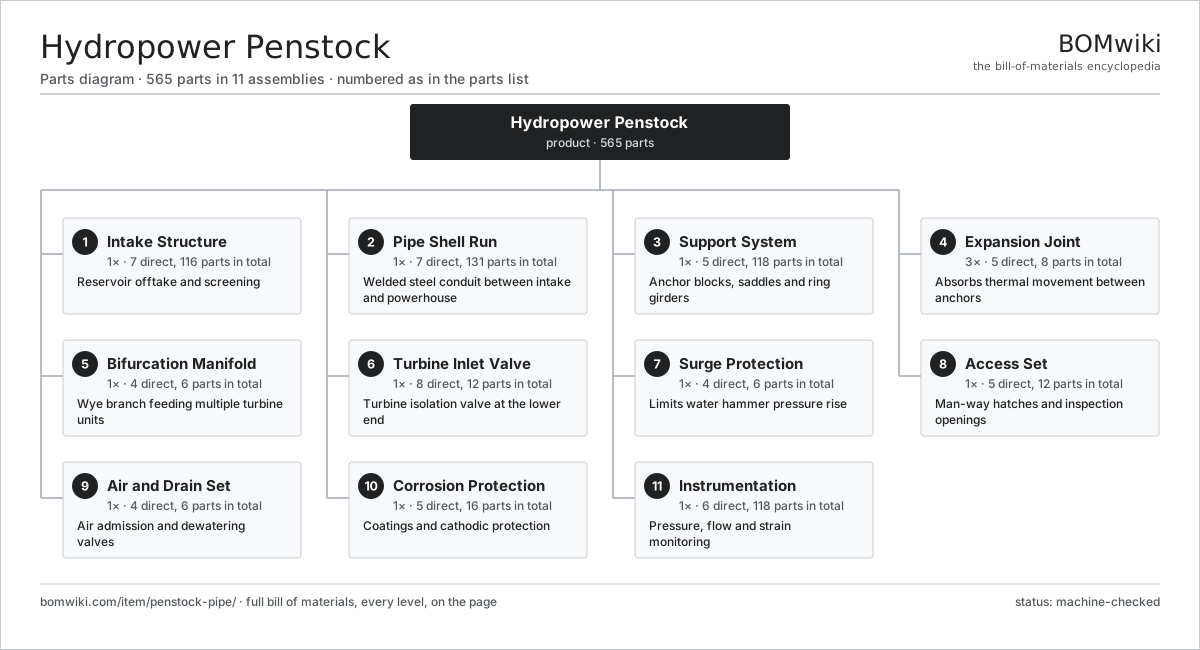
| # | Part | Qty | What it does |
|---|---|---|---|
| 1 | Intake Structure 7 parts | 1× | Reservoir offtake and screening |
| 2 | Pipe Shell Run 7 parts | 1× | Welded steel conduit between intake and powerhouse |
| 3 | Support System 5 parts | 1× | Anchor blocks, saddles and ring girders |
| 4 | Expansion Joint 5 parts | 3× | Absorbs thermal movement between anchors |
| 5 | Bifurcation Manifold 4 parts | 1× | Wye branch feeding multiple turbine units |
| 6 | Turbine Inlet Valve 8 parts | 1× | Turbine isolation valve at the lower end |
| 7 | Surge Protection 4 parts | 1× | Limits water hammer pressure rise |
| 8 | Access Set 5 parts | 1× | Man-way hatches and inspection openings |
| 9 | Air and Drain Set 4 parts | 1× | Air admission and dewatering valves |
| 10 | Corrosion Protection 5 parts | 1× | Coatings and cathodic protection |
| 11 | Instrumentation 6 parts | 1× | Pressure, flow and strain monitoring |
3D model
No 3D model yet. Have a CAD file of this? Add a 3D model — STL renders right on this page; STEP, FreeCAD, and OpenSCAD sources are welcome too (openly licensed, like all 3D models on BOMwiki).
Build & assembly graph
expand / collapse · shared sub-assemblies converge · links to related products · est. labourTap an assembly to expand/collapse · tap a part to open it · use “Open page” for any node · drag to pan, scroll to zoom.
Bill of materials for Hydropower Penstock
11 top-level lines · 105 rows shown · 565 parts total · indented to 3 levels| # | Item / sub-assembly | Part no. | Qty/assy | Ext. qty | Parts | Type |
|---|---|---|---|---|---|---|
| 1 | Intake Structure 7 parts | penstock-pipe-intake-structure | 1× | 1 | 116 | assembly |
| 1.1 | Trash Rack 3 parts | penstock-pipe-trash-rack | 1× | 1 | 62 | assembly |
| 1.1.1 | Trash Rack Bar | penstock-pipe-rack-bar | 60× | 60 | · | part |
| 1.1.2 | Trash Rack Frame | penstock-pipe-rack-frame | 1× | 1 | · | part |
| 1.1.3 | Fastener Set | fastener-set | 1× | 1 | · | part |
| 1.2 | Trash Rack Rake 4 parts | penstock-pipe-rack-rake | 1× | 1 | 27 | assembly |
| 1.2.1 | Rake Arm | penstock-pipe-rake-arm | 1× | 1 | · | part |
| 1.2.2 | Rake Hoist | penstock-pipe-rake-hoist | 1× | 1 | · | part |
| 1.2.3 | Rake Trolley | penstock-pipe-rake-trolley | 1× | 1 | · | part |
| 1.2.4 | Servo Motor 4 parts + deeper › | servo-motor | 1× | 1 | 24 | assembly |
| 1.3 | Bellmouth Entry | penstock-pipe-bellmouth-entry | 1× | 1 | · | part |
| 1.4 | Intake Gate 4 parts | penstock-pipe-intake-gate | 1× | 1 | 15 | assembly |
| 1.4.1 | Gate Leaf | penstock-pipe-gate-leaf | 1× | 1 | · | part |
| 1.4.2 | Gate Seal | penstock-pipe-gate-seal | 4× | 4 | · | part |
| 1.4.3 | Gate Roller | penstock-pipe-gate-roller | 8× | 8 | · | part |
| 1.4.4 | Gate Guide Rail | penstock-pipe-gate-guide | 2× | 2 | · | part |
| 1.5 | Gate Hoist 3 parts | penstock-pipe-gate-hoist | 1× | 1 | 9 | assembly |
| 1.5.1 | Hoist Cylinder | penstock-pipe-hoist-cylinder | 1× | 1 | · | part |
| 1.5.2 | Hydraulic Power Unit 5 parts + deeper › | penstock-pipe-hydraulic-power-unit | 1× | 1 | 6 | assembly |
| 1.5.3 | Hoist Wire Rope | penstock-pipe-hoist-rope | 2× | 2 | · | part |
| 1.6 | Stop Log Set | penstock-pipe-stop-log-set | 1× | 1 | · | part |
| 1.7 | Embedded Steel Liner | penstock-pipe-embedded-liner | 1× | 1 | · | part |
| 2 | Pipe Shell Run 7 parts | penstock-pipe-shell-run | 1× | 1 | 131 | assembly |
| 2.1 | Shell Can | penstock-pipe-shell-can | 24× | 24 | · | part |
| 2.2 | Longitudinal Seam Weld | penstock-pipe-longitudinal-weld | 24× | 24 | · | part |
| 2.3 | Girth Weld | penstock-pipe-girth-weld | 23× | 23 | · | part |
| 2.4 | Ring Stiffener | penstock-pipe-ring-stiffener | 30× | 30 | · | part |
| 2.5 | Reducer Section | penstock-pipe-reducer-section | 2× | 2 | · | part |
| 2.6 | Elbow Section | penstock-pipe-elbow-section | 4× | 4 | · | part |
| 2.7 | Flange Joint 3 parts | penstock-pipe-flange-joint | 6× | 6 | 4 | assembly |
| 2.7.1 | Weld-Neck Flange | penstock-pipe-weld-neck-flange | 2× | 12 | · | part |
| 2.7.2 | Flange Gasket | penstock-pipe-flange-gasket | 1× | 6 | · | part |
| 2.7.3 | Fastener Set | fastener-set | 1× | 6 | · | part |
| 3 | Support System 5 parts | penstock-pipe-support-system | 1× | 1 | 118 | assembly |
| 3.1 | Anchor Block 3 parts | penstock-pipe-anchor-block | 4× | 4 | 6 | assembly |
| 3.1.1 | Concrete Mass | penstock-pipe-concrete-mass | 1× | 4 | · | part |
| 3.1.2 | Anchor Reinforcement Cage | penstock-pipe-anchor-rebar | 1× | 4 | · | part |
| 3.1.3 | Anchor Strap | penstock-pipe-anchor-strap | 4× | 16 | · | part |
| 3.2 | Saddle Support 3 parts | penstock-pipe-saddle-support | 18× | 18 | 3 | assembly |
| 3.2.1 | Saddle Plate | penstock-pipe-saddle-plate | 1× | 18 | · | part |
| 3.2.2 | Wear Pad | penstock-pipe-wear-pad | 1× | 18 | · | part |
| 3.2.3 | Fastener Set | fastener-set | 1× | 18 | · | part |
| 3.3 | Thrust Collar | penstock-pipe-thrust-collar | 4× | 4 | · | part |
| 3.4 | Slide Bearing | penstock-pipe-slide-bearing | 18× | 18 | · | part |
| 3.5 | Pier Foundation | penstock-pipe-pier-foundation | 18× | 18 | · | part |
| 4 | Expansion Joint 5 parts | penstock-pipe-expansion-joint | 3× | 3 | 8 | assembly |
| 4.1 | Sliding Sleeve Section | penstock-pipe-sleeve-section | 1× | 3 | · | part |
| 4.2 | Stuffing Box | penstock-pipe-stuffing-box | 1× | 3 | · | part |
| 4.3 | Packing Ring | penstock-pipe-packing-ring | 4× | 12 | · | part |
| 4.4 | Gland Follower | penstock-pipe-gland-follower | 1× | 3 | · | part |
| 4.5 | Fastener Set | fastener-set | 1× | 3 | · | part |
| 5 | Bifurcation Manifold 4 parts | penstock-pipe-bifurcation | 1× | 1 | 6 | assembly |
| 5.1 | Wye Branch | penstock-pipe-wye-branch | 1× | 1 | · | part |
| 5.2 | Sickle Plate | penstock-pipe-sickle-plate | 1× | 1 | · | part |
| 5.3 | Branch Reinforcement | penstock-pipe-branch-reinforcement | 2× | 2 | · | part |
| 5.4 | Branch Pipe | penstock-pipe-branch-pipe | 2× | 2 | · | part |
| 6 | Turbine Inlet Valve 8 parts | penstock-pipe-inlet-valve | 1× | 1 | 12 | assembly |
| 6.1 | Valve Body | penstock-pipe-valve-body | 1× | 1 | · | part |
| 6.2 | Valve Disc | penstock-pipe-valve-disc | 1× | 1 | · | part |
| 6.3 | Valve Shaft | penstock-pipe-valve-shaft | 1× | 1 | · | part |
| 6.4 | Valve Seat | penstock-pipe-valve-seat | 2× | 2 | · | part |
| 6.5 | Valve Actuator 3 parts | penstock-pipe-valve-actuator | 1× | 1 | 3 | assembly |
| 6.5.1 | Actuator Cylinder | penstock-pipe-actuator-cylinder | 1× | 1 | · | part |
| 6.5.2 | Counterweight Arm | penstock-pipe-counterweight-arm | 1× | 1 | · | part |
| 6.5.3 | Valve Position Sensor | penstock-pipe-position-sensor | 1× | 1 | · | part |
| 6.6 | Bypass Valve | penstock-pipe-bypass-valve | 1× | 1 | · | part |
| 6.7 | Ball Bearing | ball-bearing | 2× | 2 | · | part |
| 6.8 | O-Ring Set | oring-set | 1× | 1 | · | part |
| 7 | Surge Protection 4 parts | penstock-pipe-surge-protection | 1× | 1 | 6 | assembly |
| 7.1 | Surge Tank 3 parts | penstock-pipe-surge-tank | 1× | 1 | 3 | assembly |
| 7.1.1 | Standpipe Shell | penstock-pipe-standpipe-shell | 1× | 1 | · | part |
| 7.1.2 | Surge Tank Vent | penstock-pipe-tank-vent | 1× | 1 | · | part |
| 7.1.3 | Overflow Weir | penstock-pipe-overflow-weir | 1× | 1 | · | part |
| 7.2 | Surge Orifice | penstock-pipe-surge-orifice | 1× | 1 | · | part |
| 7.3 | Pressure Relief Valve | penstock-pipe-relief-valve | 1× | 1 | · | part |
| 7.4 | Air Vessel | penstock-pipe-air-vessel | 1× | 1 | · | part |
| 8 | Access Set 5 parts | penstock-pipe-access-set | 1× | 1 | 12 | assembly |
| 8.1 | Man-Way Hatch | penstock-pipe-manway-hatch | 4× | 4 | · | part |
| 8.2 | Man-Way Cover | penstock-pipe-manway-cover | 4× | 4 | · | part |
| 8.3 | Internal Ladder | penstock-pipe-internal-ladder | 2× | 2 | · | part |
| 8.4 | O-Ring Set | oring-set | 1× | 1 | · | part |
| 8.5 | Fastener Set | fastener-set | 1× | 1 | · | part |
| 9 | Air and Drain Set 4 parts | penstock-pipe-air-drain-set | 1× | 1 | 6 | assembly |
| 9.1 | Air Valve | penstock-pipe-air-valve | 2× | 2 | · | part |
| 9.2 | Vacuum Breaker | penstock-pipe-vacuum-breaker | 1× | 1 | · | part |
| 9.3 | Drain Valve | penstock-pipe-drain-valve | 2× | 2 | · | part |
| 9.4 | Drain Sump | penstock-pipe-drain-sump | 1× | 1 | · | part |
| 10 | Corrosion Protection 5 parts | penstock-pipe-corrosion-protection | 1× | 1 | 16 | assembly |
| 10.1 | Internal Coating | penstock-pipe-internal-coating | 1× | 1 | · | part |
| 10.2 | External Coating | penstock-pipe-external-coating | 1× | 1 | · | part |
| 10.3 | Sacrificial Anode | penstock-pipe-sacrificial-anode | 12× | 12 | · | part |
| 10.4 | Anode Junction Box | penstock-pipe-anode-junction-box | 1× | 1 | · | part |
| 10.5 | Wire Bundle | wire-bundle | 1× | 1 | · | part |
| 11 | Instrumentation 6 parts | penstock-pipe-instrumentation | 1× | 1 | 118 | assembly |
| 11.1 | Pressure Sensor | pressure-sensor | 4× | 4 | · | part |
| 11.2 | Flow Meter | penstock-pipe-flow-meter | 1× | 1 | · | part |
| 11.3 | Strain Gauge | penstock-pipe-strain-gauge | 12× | 12 | · | part |
| 11.4 | Leak Detector | penstock-pipe-leak-detector | 2× | 2 | · | part |
| 11.5 | Monitoring RTU 5 parts | penstock-pipe-monitoring-rtu | 1× | 1 | 95 | assembly |
| 11.5.1 | Bare PCB | pcb-bare | 1× | 1 | · | part |
| 11.5.2 | Microcontroller | mcu | 1× | 1 | · | part |
| 11.5.3 | SMD Passive (R/C/L) | smd-passives | 80× | 80 | · | part |
| 11.5.4 | Power Supply | power-supply | 1× | 1 | · | part |
| 11.5.5 | Connector | connector | 12× | 12 | · | part |
| 11.6 | Relay | relay | 4× | 4 | · | part |
Related products
same domain, ranked by shared parts Concentrated Solar Power Receiver
855 parts · shares 15 with this page
Green Hydrogen Electrolyzer Plant
2,171 parts · shares 15 with this page
Utility-Scale Solar Inverter
204 parts · shares 15 with this page
Concentrated Solar Power Receiver
855 parts · shares 15 with this page
Green Hydrogen Electrolyzer Plant
2,171 parts · shares 15 with this page
Utility-Scale Solar Inverter
204 parts · shares 15 with this page
 Wind Turbine
28,312 parts · shares 15 with this page
Wind Turbine
28,312 parts · shares 15 with this page
 Wind Turbine Nacelle
287 parts · shares 15 with this page
Wind Turbine Nacelle
287 parts · shares 15 with this page
 Biomass Pellet Plant
404 parts · shares 14 with this page
Biomass Pellet Plant
404 parts · shares 14 with this page
Sourcing: possible vendors
Prices, MOQ, and lead times are algorithmic estimates, not quotes, and not claims about these companies. Company mappings are curated by keyword; est. price band $100–$20M. How estimates work| Vendor | HQ | Specialty | MOQ | Lead time |
|---|---|---|---|---|
|
🇩🇰Vestas
vestas.com ↗
|
Aarhus, DK | Wind turbines | 500 units | 12–24 wks |
| firstsolar.com ↗ | Tempe, US | PV modules | 500 units | 12–24 wks |
|
🇨🇳LONGi
longi.com ↗
|
Xi'an, CN | Solar wafers & modules | 500 units | 12–24 wks |
| enphase.com ↗ | Fremont, US | Microinverters & storage | 500 units | 12–24 wks |
|
🇨🇳Sungrow
sungrowpower.com ↗
|
Hefei, CN | Solar inverters & storage | 500 units | 12–24 wks |
1,044-word article