Offshore Wind Jacket Foundation
ProductOverview
A jacket foundation is a steel lattice that holds an offshore wind turbine in deeper water than a monopile can reach economically. Where the seabed is 30 to 60 metres down, a single fat tube becomes too heavy and too flexible, so the load is spread instead across four slender legs braced together into a truss, much like a fixed oil platform. The open lattice lets waves pass through rather than slamming a solid wall, which cuts the wave load and saves steel. A jacket weighs 600 to 1500 tonnes and stands 50 to 90 metres tall, anchored to the seabed by piles at each corner.
The structure divides into the frame and the systems that anchor and finish it. The four Leg legs are tied together by the Brace Network through the Node Joints where they meet. The Transition Piece caps the frame and carries the tower, the Pile Foundation anchors it, the Corrosion Protection guards the steel, the Secondary Steel provides access and cable routes, and the Monitoring System watches the fatigue-critical joints.
Legs
Each Leg is a battered tubular column, leaning inward toward the top so the base is wider and more stable. It is built like any large offshore tube, from rolled Leg Can sections cut from heavy Heavy Steel Plate in S355 steel and joined by Leg Weld girth welds. Along the leg, short Leg Stub spigots are welded on wherever a brace attaches. At the bottom the leg ends in a Pile Sleeve, a wider tube that the anchor pile will pass through. The four legs are slender on their own and only become a stiff structure once braced.
Bracing and the truss action
The legs are turned into a rigid frame by the Brace Network. Diagonal Brace tubes run at an angle between the legs, usually arranged in an X pattern in each face, and these are what carry shear and stop the frame from racking over when the wind pushes the turbine sideways. Horizontal Brace tubes ring the legs at each level to keep the bays square, and a set of Mud Brace braces just above the seabed stiffens the base. All of these are made from rolled Brace Can sections. The truss converts the bending it would otherwise see into simple tension and compression in the members, which is why a lattice can be far lighter than a solid tube of the same strength.
Node joints
Where braces meet legs are the Node Joints, and these are the heart of jacket design. At each Tubular Joint several tubes intersect, and the sharp geometry concentrates stress, so under millions of wave cycles these welds are where fatigue cracks start. Designers fight this several ways: the Node Weld profiles are ground smooth, Gusset Plate plates spread local load, and at the worst joints a thick Cast Node casting replaces the sharp welded intersection with a smooth, generous fillet. Getting these joints right is the single biggest engineering effort in a jacket, because a single fatigue failure can unzip a member.
Transition piece and the tower interface
The four legs converge into the Transition Piece, a fabricated steel deck. Each leg top seats into a Leg Pot socket on the TP Deck, and heavy Deck Girder box girders span the deck to gather the four corner loads into the single central column the tower needs. The top presents a machined Tower Flange with a Fastener Set bolt circle, identical in function to the flange on a monopile, so the same tower can sit on either foundation type.
Anchoring, protection, and monitoring
The jacket is held down by the Pile Foundation. A Pin Pile is driven through each leg sleeve deep into the seabed, then Annulus Grout is pumped into the sleeve annulus, sealed by a Grout Packer, to bond pile and sleeve into one. The Pile Stick-Up left above the sleeve is trimmed and capped. Because a jacket presents a large submerged steel area, the Corrosion Protection relies on a Coating System plus many Sacrificial Anode blocks on Anode Bracket mounts, backed by a Corrosion Allowance of spare wall. Crews reach the structure through the Secondary Steel, which adds a Boat Landing, Access Ladder climbs, External Platform decks, Handrail Set guarding, and J-Tube guides for the export cable. Finally the Monitoring System concentrates on the joints, with Strain Gauge gauges and Structural Accelerometer accelerometers reading how the lattice flexes, plus Tilt Sensor inclinometers and Corrosion Probe electrodes, all logged by an Data Logger over a Wire Bundle, so operators can track fatigue life and corrosion across the 25 to 30 year design life.
Offshore Wind Jacket Foundation parts and their functions
8 top-level parts · 489 parts in total · full bill of materials below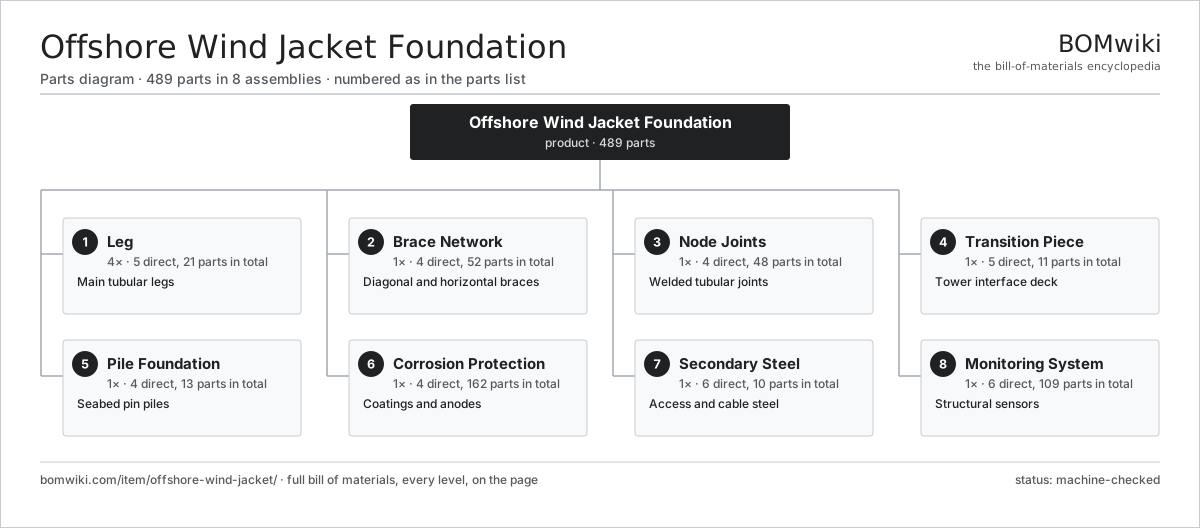
| # | Part | Qty | What it does |
|---|---|---|---|
| 1 | Leg 5 parts | 4× | Main tubular legs |
| 2 | Brace Network 4 parts | 1× | Diagonal and horizontal braces |
| 3 | Node Joints 4 parts | 1× | Welded tubular joints |
| 4 | Transition Piece 5 parts | 1× | Tower interface deck |
| 5 | Pile Foundation 4 parts | 1× | Seabed pin piles |
| 6 | Corrosion Protection 4 parts | 1× | Coatings and anodes |
| 7 | Secondary Steel 6 parts | 1× | Access and cable steel |
| 8 | Monitoring System 6 parts | 1× | Structural sensors |
3D model
No 3D model yet. Have a CAD file of this? Add a 3D model — STL renders right on this page; STEP, FreeCAD, and OpenSCAD sources are welcome too (openly licensed, like all 3D models on BOMwiki).
Build & assembly graph
expand / collapse · shared sub-assemblies converge · links to related products · est. labourTap an assembly to expand/collapse · tap a part to open it · use “Open page” for any node · drag to pan, scroll to zoom.
Bill of materials for Offshore Wind Jacket Foundation
8 top-level lines · 50 rows shown · 489 parts total · indented to 3 levels| # | Item / sub-assembly | Part no. | Qty/assy | Ext. qty | Parts | Type |
|---|---|---|---|---|---|---|
| 1 | Leg 5 parts | owj-leg-set | 4× | 4 | 21 | assembly |
| 1.1 | Leg Can | owj-leg-can | 8× | 32 | · | part |
| 1.2 | Leg Weld | owj-leg-weld | 7× | 28 | · | part |
| 1.3 | Pile Sleeve | owj-pile-sleeve | 1× | 4 | · | part |
| 1.4 | Leg Stub | owj-leg-stub | 4× | 16 | · | part |
| 1.5 | Heavy Steel Plate | owm-steel-plate | 1× | 4 | · | part |
| 2 | Brace Network 4 parts | owj-brace-network | 1× | 1 | 52 | assembly |
| 2.1 | Diagonal Brace | owj-diagonal-brace | 16× | 16 | · | part |
| 2.2 | Horizontal Brace | owj-horizontal-brace | 8× | 8 | · | part |
| 2.3 | Brace Can | owj-brace-can | 24× | 24 | · | part |
| 2.4 | Mud Brace | owj-mud-brace | 4× | 4 | · | part |
| 3 | Node Joints 4 parts | owj-node-joints | 1× | 1 | 48 | assembly |
| 3.1 | Tubular Joint | owj-tubular-joint | 16× | 16 | · | part |
| 3.2 | Cast Node | owj-cast-node | 8× | 8 | · | part |
| 3.3 | Node Weld | owj-node-weld | 16× | 16 | · | part |
| 3.4 | Gusset Plate | owj-gusset | 8× | 8 | · | part |
| 4 | Transition Piece 5 parts | owj-transition-piece | 1× | 1 | 11 | assembly |
| 4.1 | TP Deck | owj-tp-deck | 1× | 1 | · | part |
| 4.2 | Tower Flange | owm-tower-flange | 1× | 1 | · | part |
| 4.3 | Leg Pot | owj-leg-pot | 4× | 4 | · | part |
| 4.4 | Deck Girder | owj-deck-girder | 4× | 4 | · | part |
| 4.5 | Fastener Set | fastener-set | 1× | 1 | · | part |
| 5 | Pile Foundation 4 parts | owj-pile-foundation | 1× | 1 | 13 | assembly |
| 5.1 | Pin Pile | owj-pin-pile | 4× | 4 | · | part |
| 5.2 | Annulus Grout | owm-grout | 1× | 1 | · | part |
| 5.3 | Grout Packer | owj-grout-packer | 4× | 4 | · | part |
| 5.4 | Pile Stick-Up | owj-pile-stick-up | 4× | 4 | · | part |
| 6 | Corrosion Protection 4 parts | owj-corrosion-protection | 1× | 1 | 162 | assembly |
| 6.1 | Coating System | owm-coating-system | 1× | 1 | · | part |
| 6.2 | Sacrificial Anode | owm-sacrificial-anode | 80× | 80 | · | part |
| 6.3 | Anode Bracket | owj-anode-bracket | 80× | 80 | · | part |
| 6.4 | Corrosion Allowance | owm-corrosion-allowance | 1× | 1 | · | part |
| 7 | Secondary Steel 6 parts | owj-secondary-steel | 1× | 1 | 10 | assembly |
| 7.1 | Boat Landing | owm-boat-landing | 1× | 1 | · | part |
| 7.2 | Access Ladder | owm-access-ladder | 3× | 3 | · | part |
| 7.3 | External Platform | owm-external-platform | 2× | 2 | · | part |
| 7.4 | J-Tube | owm-j-tube | 2× | 2 | · | part |
| 7.5 | Handrail Set | owm-handrail | 1× | 1 | · | part |
| 7.6 | Fastener Set | fastener-set | 1× | 1 | · | part |
| 8 | Monitoring System 6 parts | owj-monitoring-system | 1× | 1 | 109 | assembly |
| 8.1 | Strain Gauge | owm-strain-gauge | 12× | 12 | · | part |
| 8.2 | Structural Accelerometer | owj-accelerometer | 4× | 4 | · | part |
| 8.3 | Tilt Sensor | owm-tilt-sensor | 2× | 2 | · | part |
| 8.4 | Corrosion Probe | owm-corrosion-probe | 4× | 4 | · | part |
| 8.5 | Data Logger 4 parts | owm-data-logger | 1× | 1 | 86 | assembly |
| 8.5.1 | Bare PCB | pcb-bare | 1× | 1 | · | part |
| 8.5.2 | Microcontroller | mcu | 1× | 1 | · | part |
| 8.5.3 | SMD Passive (R/C/L) | smd-passives | 80× | 80 | · | part |
| 8.5.4 | Connector | connector | 4× | 4 | · | part |
| 8.6 | Wire Bundle | wire-bundle | 1× | 1 | · | part |
Sourcing: possible vendors
Prices, MOQ, and lead times are algorithmic estimates, not quotes, and not claims about these companies. Company mappings are curated by keyword; est. price band $100–$20M. How estimates work| Vendor | HQ | Specialty | MOQ | Lead time |
|---|---|---|---|---|
|
🇩🇰Vestas
vestas.com ↗
|
Aarhus, DK | Wind turbines | 500 units | 12–24 wks |
| firstsolar.com ↗ | Tempe, US | PV modules | 500 units | 12–24 wks |
|
🇨🇳LONGi
longi.com ↗
|
Xi'an, CN | Solar wafers & modules | 500 units | 12–24 wks |
| enphase.com ↗ | Fremont, US | Microinverters & storage | 500 units | 12–24 wks |
|
🇨🇳Sungrow
sungrowpower.com ↗
|
Hefei, CN | Solar inverters & storage | 500 units | 12–24 wks |
821-word article