Wind Turbine Yaw Drive
ProductOverview
The yaw drive is what keeps a wind turbine pointed into the wind. A horizontal-axis turbine only makes full power when its rotor faces the wind squarely, but the wind shifts direction constantly, so the entire nacelle, weighing many tonnes with the rotor on its nose, has to be slowly swung around the top of the tower to track it. The yaw drive does this with several geared electric motors that grip a large toothed ring and walk the nacelle around, plus brakes that lock it in place once it is aligned so gusts cannot push it off heading.
The system is a set of cooperating parts. Several Yaw Drive Unit actuators provide the muscle, meshing the Yaw Bearing slewing ring that both supports and turns the nacelle. The Yaw Brake System holds the heading, the Yaw Control System decides when to move, the Wind Sensing tells it where the wind is, the Lubrication System keeps the teeth greased, and the Cable Management stops the cables from twisting apart as the nacelle turns.
Drive units
The force to swing the nacelle comes from four to eight Yaw Drive Unit actuators spaced around the ring, working together so no single unit is overloaded. Each starts with a Yaw Motor, an electric motor that spins fast at low torque. That feeds a Planetary Gearbox, a high-ratio planetary reducer often close to a thousand to one, built from stacked Planet Set stages around a Sun Pinion inside a Internal Ring Gear ring. The reduction trades the motor's speed for the enormous torque needed to move the nacelle, delivered through the Output Pinion that meshes the yaw ring. A Holding Brake on each motor lets the drives rest without the load creeping back.
Yaw bearing
The Yaw Bearing is the single large interface between the fixed tower and the turning nacelle. It is a Slewing Ring, a roller bearing two to three metres across running on Bearing Roller elements, that carries the full weight and tipping load of the nacelle while letting it rotate freely. The clever part is that the ring also carries Yaw Ring Gear, gear teeth cut directly into it, so the same component that supports the nacelle is also the gear the drives push against. Bearing Seal lip seals keep grease in and the weather out of the raceway, and a heavy Fastener Set bolts the ring between the tower top and the nacelle bedplate.
Holding the heading
Once aligned, the nacelle must hold still against gusts that would otherwise hammer the gear teeth back and forth, which is the job of the Yaw Brake System. A ring of Yaw Brake Caliper hydraulic calipers, each built from a Caliper Body and Caliper Piston set, clamps the steel Yaw Brake Disc through Yaw Brake Pad friction pads. Pressure comes from the Hydraulic Power Unit, where a Hydraulic Pump and gas-charged Hydraulic Accumulator feed the calipers through Brake Hose lines. During a yaw move the calipers release just enough to let the nacelle turn under a residual drag, which keeps the motion smooth and stops the teeth from rattling.
Sensing and control
The decision to yaw is made by the Yaw Control System. A Yaw Controller reads the wind and compares it to the nacelle heading reported by a Position Encoder, then commands the motors through a Motor Drive for each unit. Those drives, built around a Power Switch and Gate Driver, soft-start the motors so they ramp up gently instead of slamming the gear teeth, and Relay contactors switch them on and off. The wind information itself comes from the Wind Sensing pack on the nacelle roof: a Wind Vane gives direction and an Anemometer gives speed, both kept clear by a Sensor Heater. The controller deliberately tolerates small misalignment rather than chasing every gust, because constant yawing wears the drive and gives little extra energy.
Lubrication and cable handling
The open ring teeth and the slewing raceway sit exposed to weather under heavy, slow load, so the Lubrication System system greases them automatically: a Grease Pump meters Lubricating Grease through a Grease Distributor and Grease Line feeds to each point on a schedule. Finally, because the nacelle can rotate many full turns over time, the power and signal cables running up from the fixed tower would twist off if nothing managed them. The Cable Management handles this with a hanging Cable Loop of slack that absorbs several turns, supported by Cable Clamp clamps on a Cable Ladder. A Twist Counter keeps a running tally of net turns, and when the cable has wound up to its limit the controller deliberately yaws the nacelle back the other way to untwist it, even at the cost of a brief misalignment.
Wind Turbine Yaw Drive parts and their functions
7 top-level parts · 1,216 parts in total · full bill of materials below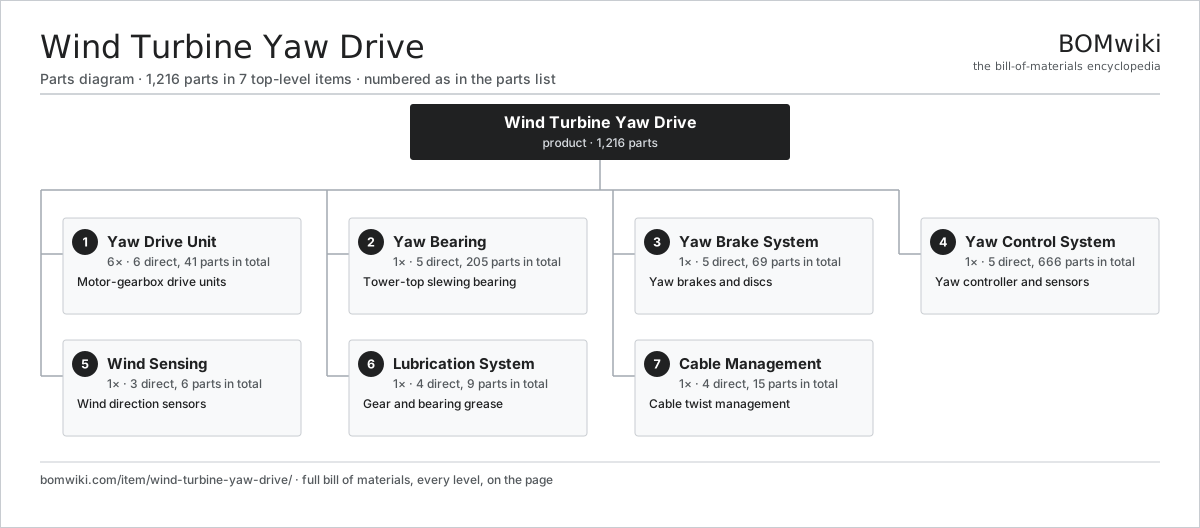
| # | Part | Qty | What it does |
|---|---|---|---|
| 1 | Yaw Drive Unit 6 parts | 6× | Motor-gearbox drive units |
| 2 | Yaw Bearing 5 parts | 1× | Tower-top slewing bearing |
| 3 | Yaw Brake System 5 parts | 1× | Yaw brakes and discs |
| 4 | Yaw Control System 5 parts | 1× | Yaw controller and sensors |
| 5 | Wind Sensing 3 parts | 1× | Wind direction sensors |
| 6 | Lubrication System 4 parts | 1× | Gear and bearing grease |
| 7 | Cable Management 4 parts | 1× | Cable twist management |
3D model
No 3D model yet. Have a CAD file of this? Add a 3D model. STL renders right on this page; STEP, FreeCAD, and OpenSCAD sources are welcome too (openly licensed, like all 3D models on BOMwiki).
Build & assembly graph
expand / collapse · shared sub-assemblies converge · links to related products · est. labourTap an assembly to expand/collapse · tap a part to open it · use “Open page” for any node · drag to pan, scroll to zoom.
Bill of materials for Wind Turbine Yaw Drive
7 top-level lines · 64 rows shown · 1,216 parts total · indented to 3 levels| # | Item / sub-assembly | Part no. | Qty/assy | Ext. qty | Parts | Type |
|---|---|---|---|---|---|---|
| 1 | Yaw Drive Unit 6 parts | wyd-yaw-drive-unit | 6× | 6 | 41 | assembly |
| 1.1 | Yaw Motor 4 parts | wyd-yaw-motor | 1× | 6 | 25 | assembly |
| 1.1.1 | Stator Assembly 3 parts + deeper › | stator-assembly | 1× | 6 | 3 | assembly |
| 1.1.2 | Rotor Assembly 4 parts + deeper › | rotor-assembly | 1× | 6 | 19 | assembly |
| 1.1.3 | Motor Housing | motor-housing | 1× | 6 | · | part |
| 1.1.4 | Ball Bearing | ball-bearing | 2× | 12 | · | part |
| 1.2 | Planetary Gearbox 5 parts | wyd-planetary-gearbox | 1× | 6 | 10 | assembly |
| 1.2.1 | Planet Set | wyd-planet-set | 3× | 18 | · | part |
| 1.2.2 | Sun Pinion | wyd-sun-pinion | 1× | 6 | · | part |
| 1.2.3 | Internal Ring Gear | wyd-ring-internal | 1× | 6 | · | part |
| 1.2.4 | Gearbox Housing | gearbox-housing | 1× | 6 | · | part |
| 1.2.5 | Ball Bearing | ball-bearing | 4× | 24 | · | part |
| 1.3 | Output Pinion | wyd-output-pinion | 1× | 6 | · | part |
| 1.4 | Holding Brake | wyd-holding-brake | 1× | 6 | · | part |
| 1.5 | Ball Bearing | ball-bearing | 2× | 12 | · | part |
| 1.6 | Oil Seal | oil-seal | 2× | 12 | · | part |
| 2 | Yaw Bearing 5 parts | wyd-yaw-bearing | 1× | 1 | 205 | assembly |
| 2.1 | Slewing Ring | wyd-slewing-ring | 1× | 1 | · | part |
| 2.2 | Yaw Ring Gear | wyd-ring-gear-teeth | 1× | 1 | · | part |
| 2.3 | Bearing Roller | wyd-bearing-roller | 200× | 200 | · | part |
| 2.4 | Bearing Seal | wyd-bearing-seal | 2× | 2 | · | part |
| 2.5 | Fastener Set | fastener-set | 1× | 1 | · | part |
| 3 | Yaw Brake System 5 parts | wyd-brake-system | 1× | 1 | 69 | assembly |
| 3.1 | Yaw Brake Caliper 3 parts | wyd-brake-caliper | 8× | 8 | 5 | assembly |
| 3.1.1 | Caliper Body | wyd-caliper-body | 1× | 8 | · | part |
| 3.1.2 | Caliper Piston | wyd-caliper-piston | 2× | 16 | · | part |
| 3.1.3 | O-Ring Set | oring-set | 2× | 16 | · | part |
| 3.2 | Yaw Brake Disc | wyd-brake-disc | 1× | 1 | · | part |
| 3.3 | Yaw Brake Pad | wyd-brake-pad | 16× | 16 | · | part |
| 3.4 | Hydraulic Power Unit 4 parts | wyd-hydraulic-unit | 1× | 1 | 4 | assembly |
| 3.4.1 | Hydraulic Pump | wyd-hyd-pump | 1× | 1 | · | part |
| 3.4.2 | Hydraulic Accumulator | wyd-accumulator | 1× | 1 | · | part |
| 3.4.3 | Pressure Sensor | pressure-sensor | 1× | 1 | · | part |
| 3.4.4 | O-Ring Set | oring-set | 1× | 1 | · | part |
| 3.5 | Brake Hose | wyd-brake-hose | 8× | 8 | · | part |
| 4 | Yaw Control System 5 parts | wyd-control-system | 1× | 1 | 666 | assembly |
| 4.1 | Yaw Controller 4 parts | wyd-yaw-controller | 1× | 1 | 128 | assembly |
| 4.1.1 | Bare PCB | pcb-bare | 1× | 1 | · | part |
| 4.1.2 | Microcontroller | mcu | 1× | 1 | · | part |
| 4.1.3 | SMD Passive (R/C/L) | smd-passives | 120× | 120 | · | part |
| 4.1.4 | Connector | connector | 6× | 6 | · | part |
| 4.2 | Motor Drive 4 parts | wyd-motor-drive | 6× | 6 | 88 | assembly |
| 4.2.1 | Bare PCB | pcb-bare | 1× | 6 | · | part |
| 4.2.2 | Power Switch | wyd-power-switch | 6× | 36 | · | part |
| 4.2.3 | Gate Driver | wyd-gate-driver | 1× | 6 | · | part |
| 4.2.4 | SMD Passive (R/C/L) | smd-passives | 80× | 480 | · | part |
| 4.3 | Position Encoder | wyd-position-encoder | 1× | 1 | · | part |
| 4.4 | Relay | relay | 8× | 8 | · | part |
| 4.5 | Wire Bundle | wire-bundle | 1× | 1 | · | part |
| 5 | Wind Sensing 3 parts | wyd-wind-sensing | 1× | 1 | 6 | assembly |
| 5.1 | Wind Vane | wyd-wind-vane | 2× | 2 | · | part |
| 5.2 | Anemometer | wyd-anemometer | 2× | 2 | · | part |
| 5.3 | Sensor Heater 1 parts | wyd-sensor-heater | 2× | 2 | 1 | assembly |
| 5.3.1 | Heating Element | heating-element | 1× | 2 | · | part |
| 6 | Lubrication System 4 parts | wyd-lubrication | 1× | 1 | 9 | assembly |
| 6.1 | Grease Pump | wyd-grease-pump | 1× | 1 | · | part |
| 6.2 | Grease Distributor | wyd-grease-distributor | 1× | 1 | · | part |
| 6.3 | Lubricating Grease | wyd-grease | 1× | 1 | · | part |
| 6.4 | Grease Line | wyd-grease-line | 6× | 6 | · | part |
| 7 | Cable Management 4 parts | wyd-cable-management | 1× | 1 | 15 | assembly |
| 7.1 | Cable Loop | wyd-cable-loop | 1× | 1 | · | part |
| 7.2 | Twist Counter | wyd-twist-counter | 1× | 1 | · | part |
| 7.3 | Cable Clamp | wyd-cable-clamp | 12× | 12 | · | part |
| 7.4 | Cable Ladder | wyd-cable-ladder | 1× | 1 | · | part |
Something wrong in this list? Report a problem with this BOM.
Used in 1 assembly
Related products
same domain, ranked by shared parts Wind Turbine
28,312 parts · shares 16 with this page
 Wind Turbine Pitch System
1,566 parts · shares 14 with this page
 Wind Turbine Nacelle
287 parts · shares 15 with this page
 Concentrated Solar Power Receiver
855 parts · shares 14 with this page
Green Hydrogen Electrolyzer Plant
2,171 parts · shares 14 with this page
Utility-Scale Solar Inverter
204 parts · shares 14 with this page
Sourcing: possible vendors
Browse the supplier directory → Prices, MOQ, and lead times are algorithmic estimates, not quotes, and not claims about these companies. Company mappings are curated by keyword; est. price band $100–$20M. How estimates work| Vendor | HQ | Specialty | MOQ | Lead time |
|---|---|---|---|---|
|
🇩🇰Vestas
vestas.com ↗
|
Aarhus, DK | Wind turbines | 500 units | 12–24 wks |
| firstsolar.com ↗ | Tempe, US | PV modules | 500 units | 12–24 wks |
|
🇨🇳LONGi
longi.com ↗
|
Xi'an, CN | Solar wafers & modules | 500 units | 12–24 wks |
| enphase.com ↗ | Fremont, US | Microinverters & storage | 500 units | 12–24 wks |
|
🇨🇳Sungrow
sungrowpower.com ↗
|
Hefei, CN | Solar inverters & storage | 500 units | 12–24 wks |
831-word article