Grid-Forming Inverter
ProductOverview
A grid-forming inverter converts DC power from a battery or solar array into three-phase AC and, unlike a conventional grid-following inverter, it actively establishes the voltage magnitude and frequency of the AC system rather than measuring them from an existing grid. Utility-scale units rated from 1 to 4 MW operate from a 900–1500 V DC bus and deliver 400–690 V AC, which a step-up transformer then raises to medium or high voltage. The inverter behaves like a controlled voltage source behind an impedance, so it can energize a network with no other generation present, ride through faults, and share load with synchronous machines. This capability matters as conventional power stations retire and inverter-based resources supply a larger share of generation, because the system still needs a source that defines frequency and supplies inertia-like response.
The Control and DSP Board is the element that distinguishes a grid-forming machine. It runs a virtual synchronous machine or droop algorithm that computes the voltage waveform the inverter should produce, then commands the Power Module to synthesize it. The remaining subsystems handle power conversion, filtering, protection, and heat removal in the same way as any large inverter.
Grid-forming versus grid-following control
A grid-following inverter uses a phase-locked loop to track the existing grid voltage and injects a commanded current in phase with it. It cannot operate if the grid is absent or weak. A grid-forming inverter instead generates an internal voltage phasor with its own frequency and angle, and the power it exchanges follows from the angle and magnitude difference between that internal voltage and the grid. Active power is governed by a frequency-versus-power droop, typically 2–5 percent, and reactive power by a voltage-versus-reactive droop. When grid frequency falls, the controller increases power output within the limits of the DC source; when frequency rises, it backs off. This mirrors how a synchronous generator responds and lets several grid-forming units share load without fast communication between them. The Sensing and Protection subsystem feeds isolated current and voltage measurements into the control loop at high sample rates so the algorithm can regulate the output and detect faults within a fraction of a cycle.
Power stage
The conversion core is a three-phase two-level or three-level bridge. High-performance units use silicon carbide MOSFET modules in the Power Module, switching at 4–20 kHz, which raises efficiency to roughly 98.5–99.0 percent and shrinks the magnetics; IGBT designs switch at 2–4 kHz and cost less. Each phase leg uses isolated gate drivers with desaturation protection, and film DC link capacitors stabilize the bus and absorb ripple current. Power enters through the DC Input Stage, which carries the 1500 V bus on a laminated busbar, protects it with high-speed fuses and surge devices, and limits capacitor inrush with a pre-charge resistor that a relay bypasses once the bus is charged. An insulation monitor checks resistance to ground before the unit connects.
Output filter and magnetics
Switching produces voltage steps that must be filtered before the current reaches the grid. The LCL Output Filter is an LCL network: an inverter-side inductor, a shunt capacitor, and a grid-side inductor per phase. This third-order filter attenuates switching harmonics far more steeply than a single inductor, which keeps current total harmonic distortion below 3 percent at rated load while using smaller, lighter inductors. The trade is a resonant peak, so passive damping resistors are placed in series with the filter capacitors, or active damping is implemented in firmware. The inductor cores are sized to avoid saturation at the peak fault current the inverter may push during a grid disturbance.
Cooling and protection
Power module losses of tens of kilowatts at full load are removed by the Cooling System, a water-glycol loop that pumps coolant through cold plates clamped to the modules and rejects heat through a liquid-to-air heat exchanger. Coolant enters the plates at 40–55 °C and a flow switch interlocks the inverter so it cannot run dry. On the grid side, the AC Output Stage holds the synchronizing contactor, a molded case breaker for fault clearing, and surge arrestors on each phase. The Cabinet Enclosure is an outdoor-rated steel cabinet with door interlocks, ventilation, main busbars, and an HMI touchscreen, and the Auxiliary Power Supplies supplies feed the gate drivers and controls, with a backup source that holds the controller alive through grid voltage dips.
Control and use
In a battery storage plant, the grid-forming inverter can black-start a network, supply fast frequency response, and form a stable island during an outage, then resynchronize when the wider grid returns. Anti-islanding and over and under frequency protection, handled in the Sensing and Protection relays, govern when the unit disconnects from a utility tie. Commissioning follows IEEE 1547 and IEEE 2800 for interconnection, with droop coefficients, fault current contribution, and ride-through curves configured to the plant operator and the local grid code.
Grid-Forming Inverter parts and their functions
9 top-level parts · 165 parts in total · full bill of materials below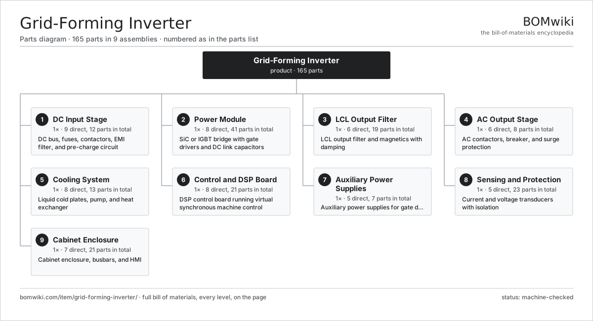
| # | Part | Qty | What it does |
|---|---|---|---|
| 1 | DC Input Stage 9 parts | 1× | DC bus, fuses, contactors, EMI filter, and pre-charge circuit |
| 2 | Power Module 8 parts | 1× | SiC or IGBT bridge with gate drivers and DC link capacitors |
| 3 | LCL Output Filter 6 parts | 1× | LCL output filter and magnetics with damping |
| 4 | AC Output Stage 6 parts | 1× | AC contactors, breaker, and surge protection |
| 5 | Cooling System 8 parts | 1× | Liquid cold plates, pump, and heat exchanger |
| 6 | Control and DSP Board 8 parts | 1× | DSP control board running virtual synchronous machine control |
| 7 | Auxiliary Power Supplies 5 parts | 1× | Auxiliary power supplies for gate drivers and controls |
| 8 | Sensing and Protection 5 parts | 1× | Current and voltage transducers with isolation |
| 9 | Cabinet Enclosure 7 parts | 1× | Cabinet enclosure, busbars, and HMI |
3D model
No 3D model yet. Have a CAD file of this? Add a 3D model — STL renders right on this page; STEP, FreeCAD, and OpenSCAD sources are welcome too (openly licensed, like all 3D models on BOMwiki).
Build & assembly graph
expand / collapse · shared sub-assemblies converge · links to related products · est. labourTap an assembly to expand/collapse · tap a part to open it · use “Open page” for any node · drag to pan, scroll to zoom.
Bill of materials for Grid-Forming Inverter
9 top-level lines · 71 rows shown · 165 parts total · indented to 3 levels| # | Item / sub-assembly | Part no. | Qty/assy | Ext. qty | Parts | Type |
|---|---|---|---|---|---|---|
| 1 | DC Input Stage 9 parts | grid-forming-inverter-dc-input-stage | 1× | 1 | 12 | assembly |
| 1.1 | DC Busbar | grid-forming-inverter-dc-busbar | 1× | 1 | · | part |
| 1.2 | DC Fuse | grid-forming-inverter-dc-fuse | 2× | 2 | · | part |
| 1.3 | DC Contactor | grid-forming-inverter-dc-contactor | 2× | 2 | · | part |
| 1.4 | Pre-charge Resistor | grid-forming-inverter-precharge-resistor | 1× | 1 | · | part |
| 1.5 | Pre-charge Relay | grid-forming-inverter-precharge-relay | 1× | 1 | · | part |
| 1.6 | DC EMI Filter | grid-forming-inverter-dc-emi-filter | 1× | 1 | · | part |
| 1.7 | DC Surge Protector | grid-forming-inverter-dc-spd | 2× | 2 | · | part |
| 1.8 | DC Disconnect Switch | grid-forming-inverter-dc-disconnect | 1× | 1 | · | part |
| 1.9 | Insulation Monitor | grid-forming-inverter-insulation-monitor | 1× | 1 | · | part |
| 2 | Power Module 8 parts | grid-forming-inverter-power-module | 1× | 1 | 41 | assembly |
| 2.1 | SiC Power Module | grid-forming-inverter-sic-module | 6× | 6 | · | part |
| 2.2 | Gate Driver Board | grid-forming-inverter-gate-driver | 6× | 6 | · | part |
| 2.3 | DC Link Capacitor | grid-forming-inverter-dc-link-cap | 12× | 12 | · | part |
| 2.4 | Laminated Busbar Stack | grid-forming-inverter-busbar-stack | 1× | 1 | · | part |
| 2.5 | Power Module Cold Plate | grid-forming-inverter-cold-plate | 3× | 3 | · | part |
| 2.6 | Snubber Network | grid-forming-inverter-snubber | 6× | 6 | · | part |
| 2.7 | Module Clamp | grid-forming-inverter-module-clamp | 6× | 6 | · | part |
| 2.8 | Fastener Set | fastener-set | 1× | 1 | · | part |
| 3 | LCL Output Filter 6 parts | grid-forming-inverter-output-filter | 1× | 1 | 19 | assembly |
| 3.1 | Inverter-side Inductor | grid-forming-inverter-inverter-inductor | 3× | 3 | · | part |
| 3.2 | Grid-side Inductor | grid-forming-inverter-grid-inductor | 3× | 3 | · | part |
| 3.3 | AC Filter Capacitor | grid-forming-inverter-filter-cap | 3× | 3 | · | part |
| 3.4 | Damping Resistor | grid-forming-inverter-damping-resistor | 3× | 3 | · | part |
| 3.5 | Filter Inductor Core | grid-forming-inverter-filter-core | 6× | 6 | · | part |
| 3.6 | Filter Mounting Bracket | grid-forming-inverter-filter-mount | 1× | 1 | · | part |
| 4 | AC Output Stage 6 parts | grid-forming-inverter-ac-output-stage | 1× | 1 | 8 | assembly |
| 4.1 | AC Contactor | grid-forming-inverter-ac-contactor | 1× | 1 | · | part |
| 4.2 | AC Circuit Breaker | grid-forming-inverter-ac-breaker | 1× | 1 | · | part |
| 4.3 | AC Output Busbar | grid-forming-inverter-ac-busbar | 1× | 1 | · | part |
| 4.4 | AC Surge Arrestor | grid-forming-inverter-ac-spd | 3× | 3 | · | part |
| 4.5 | AC Terminal Block | grid-forming-inverter-ac-terminal | 1× | 1 | · | part |
| 4.6 | AC Pre-insertion Resistor | grid-forming-inverter-precharge-ac | 1× | 1 | · | part |
| 5 | Cooling System 8 parts | grid-forming-inverter-cooling-system | 1× | 1 | 13 | assembly |
| 5.1 | Coolant Pump | grid-forming-inverter-coolant-pump | 1× | 1 | · | part |
| 5.2 | Heat Exchanger | grid-forming-inverter-heat-exchanger | 1× | 1 | · | part |
| 5.3 | Coolant Expansion Tank | grid-forming-inverter-expansion-tank | 1× | 1 | · | part |
| 5.4 | Coolant Hose | grid-forming-inverter-coolant-hose | 4× | 4 | · | part |
| 5.5 | Coolant Flow Switch | grid-forming-inverter-flow-switch | 1× | 1 | · | part |
| 5.6 | Pressure Sensor | pressure-sensor | 1× | 1 | · | part |
| 5.7 | Heat Exchanger Fan | grid-forming-inverter-fan | 2× | 2 | · | part |
| 5.8 | Ball Bearing | ball-bearing | 2× | 2 | · | part |
| 6 | Control and DSP Board 8 parts | grid-forming-inverter-control-board | 1× | 1 | 21 | assembly |
| 6.1 | Bare PCB | pcb-bare | 1× | 1 | · | part |
| 6.2 | Microcontroller | mcu | 1× | 1 | · | part |
| 6.3 | PWM FPGA | grid-forming-inverter-fpga | 1× | 1 | · | part |
| 6.4 | SMD Passive (R/C/L) | smd-passives | 1× | 1 | · | part |
| 6.5 | Isolated ADC | grid-forming-inverter-adc | 4× | 4 | · | part |
| 6.6 | Communications Module | grid-forming-inverter-comms-module | 1× | 1 | · | part |
| 6.7 | Connector | connector | 6× | 6 | · | part |
| 6.8 | Fiber Optic Link | grid-forming-inverter-fiber-link | 6× | 6 | · | part |
| 7 | Auxiliary Power Supplies 5 parts | grid-forming-inverter-aux-power | 1× | 1 | 7 | assembly |
| 7.1 | Power Supply | power-supply | 2× | 2 | · | part |
| 7.2 | Auxiliary Transformer | grid-forming-inverter-aux-transformer | 1× | 1 | · | part |
| 7.3 | Control UPS | grid-forming-inverter-ups | 1× | 1 | · | part |
| 7.4 | Auxiliary Breaker | grid-forming-inverter-aux-breaker | 2× | 2 | · | part |
| 7.5 | Wire Bundle | wire-bundle | 1× | 1 | · | part |
| 8 | Sensing and Protection 5 parts | grid-forming-inverter-sensing | 1× | 1 | 23 | assembly |
| 8.1 | Current Transducer | grid-forming-inverter-current-transducer | 6× | 6 | · | part |
| 8.2 | Voltage Transducer | grid-forming-inverter-voltage-transducer | 6× | 6 | · | part |
| 8.3 | Temperature Sensor | grid-forming-inverter-temp-sensor | 6× | 6 | · | part |
| 8.4 | Protection Relay | grid-forming-inverter-protection-relay | 1× | 1 | · | part |
| 8.5 | Relay | relay | 4× | 4 | · | part |
| 9 | Cabinet Enclosure 7 parts | grid-forming-inverter-enclosure | 1× | 1 | 21 | assembly |
| 9.1 | Sheet Metal Panel | sheet-panel | 6× | 6 | · | part |
| 9.2 | Main Busbar | grid-forming-inverter-main-busbar | 1× | 1 | · | part |
| 9.3 | Door Interlock | grid-forming-inverter-door-interlock | 2× | 2 | · | part |
| 9.4 | LCD Panel | lcd-panel | 1× | 1 | · | part |
| 9.5 | Cabinet Ventilation Fan | grid-forming-inverter-cabinet-fan | 2× | 2 | · | part |
| 9.6 | Cable Gland | grid-forming-inverter-cable-gland | 8× | 8 | · | part |
| 9.7 | Fastener Set | fastener-set | 1× | 1 | · | part |
Related products
same domain, ranked by shared parts PEM Hydrogen Electrolyzer
305 parts · shares 5 with this page
Utility-Scale Solar Inverter
204 parts · shares 5 with this page
PEM Hydrogen Electrolyzer
305 parts · shares 5 with this page
Utility-Scale Solar Inverter
204 parts · shares 5 with this page
 Wind Turbine
28,312 parts · shares 5 with this page
Wind Turbine
28,312 parts · shares 5 with this page
 Wind Turbine Nacelle
287 parts · shares 5 with this page
Wind Turbine Nacelle
287 parts · shares 5 with this page
 Battery Energy Storage System
17,429 parts · shares 4 with this page
Battery Energy Storage System
17,429 parts · shares 4 with this page
Sourcing: possible vendors
Prices, MOQ, and lead times are algorithmic estimates, not quotes, and not claims about these companies. Company mappings are curated by keyword; est. price band $100–$20M. How estimates work| Vendor | HQ | Specialty | MOQ | Lead time |
|---|---|---|---|---|
|
🇩🇰Vestas
vestas.com ↗
|
Aarhus, DK | Wind turbines | 500 units | 12–24 wks |
| firstsolar.com ↗ | Tempe, US | PV modules | 500 units | 12–24 wks |
|
🇨🇳LONGi
longi.com ↗
|
Xi'an, CN | Solar wafers & modules | 500 units | 12–24 wks |
| enphase.com ↗ | Fremont, US | Microinverters & storage | 500 units | 12–24 wks |
|
🇨🇳Sungrow
sungrowpower.com ↗
|
Hefei, CN | Solar inverters & storage | 500 units | 12–24 wks |
873-word article