Francis Hydro Turbine
ProductOverview
A Francis turbine is the workhorse of medium-head hydropower, the type installed in most large dam powerhouses around the world. It is a reaction machine, meaning the runner sits in a fully flooded passage and takes torque from a pressure drop across its blades rather than from a free jet. Water enters around the rim, flows inward through the blades while turning from radial to axial, and leaves downward through a draft tube. Because the runner works on both the pressure and the velocity of the water, a Francis machine covers a wide head and flow range and reaches efficiencies above 94 percent, higher than the impulse Pelton Hydro Turbine and overlapping the low-head Kaplan Hydro Turbine.
Water arrives through the penstock and the Spiral Casing, which distributes it evenly around the runner. The Wicket Gate Ring meter the flow and set its swirl before it enters the Runner, where torque is developed and passed up the Shaft Line to the generator. The Draft Tube below recovers energy from the leaving water. Speed is held by the Governor, leakage is limited by the Sealing System, and the Lubrication Unit unit and Control Cabinet cabinet keep the unit fed and supervised.
The runner
The Runner converts the flow into shaft torque. It is a single casting in which a ring of doubly curved Runner Blade surfaces spans between an upper Runner Crown and a lower Runner Band. Each blade turns the water from a radial inward direction to an axial downward one, and the pressure difference between the two faces of every blade produces the torque. The blade geometry is specific to the site head and flow, which is why a Francis runner is described by its specific speed: low-head runners are wide and flat, high-head runners are narrow and tall. The whole runner is cast in 13-4 stainless steel to resist cavitation and locks to the shaft through the Runner Hub. Cavitation, the formation and collapse of vapour bubbles where local pressure drops too low, is the main wear mechanism and drives both the blade material choice and the depth at which the runner is set below tailwater.
Water supply and flow control
The Spiral Casing is a steel volute of steadily shrinking section, sized so that the same flow passes every part of the rim and the water enters the runner symmetrically. Its Volute Shell joins the penstock at the Inlet Flange, and a Stay Ring with fixed Stay Vane members carries the casing load while beginning to turn the flow. The real control element is the Wicket Gate Ring ring, a set of pivoting Guide Vane members just outside the runner. Each vane carries a Vane Lever linked to a common Operating Ring, so rotating that ring opens or closes every vane together to set the flow and the swirl angle into the runner. The vanes turn in Vane Bushing supports, and a Shear Pin in each linkage breaks to save the mechanism if a vane jams on debris.
Energy recovery and sealing
Below the runner the Draft Tube does more than carry water away. Its Draft Cone diverges so the leaving water slows down, which converts the remaining velocity into a pressure recovery and lowers the pressure at the runner outlet, raising the effective head the machine works across. The Draft Elbow then turns the flow to the tailrace, protected by a Draft Liner, and a Aeration Valve admits air to damp the vortex rope that forms in the cone at part load. Leakage around the runner is held down by renewable Wear Ring pairs that set a tight running clearance, while the Shaft Seal where the shaft passes the head cover is cooled and flushed by the Seal Water Unit unit.
Shaft line, governing, and auxiliaries
Most large Francis units are vertical, with the runner at the bottom and the generator above. The forged Main Shaft runs in an oil-film Guide Bearing and joins the generator through a Coupling. The Governor holds speed to fix grid frequency: a Governor Pump keeps oil pressurised, a Accumulator stores energy for fast moves, and large Gate Servomotor cylinders rotate the operating ring to drive the guide vanes. A Speed Pickup reads runner speed and the Governor Controller closes the loop. The Lubrication Unit unit circulates filtered oil through the Oil Cooler with its Lube Pump and Oil Filter elements, and the Control Cabinet cabinet sequences the unit through its Unit PLC while a Vibration Monitor guards against runaway and rough running.
Where Francis turbines fit
The Francis turbine covers the broadest middle ground in hydropower, from about 40 metres of head up to 700 metres and from small run-of-river units to single machines of several hundred megawatts. Above its head range the Pelton Hydro Turbine takes over, where converting the whole head to a jet is more efficient than running a flooded runner. Below its range the propeller-type Kaplan Hydro Turbine and the bulb-turbine handle low head and high flow, and reversible Pumped Storage Pump-Turbine machines, themselves Francis runners designed to run both ways, store energy by pumping uphill when power is cheap. Within its band the Francis machine combines high efficiency, a wide operating window, and a compact powerhouse, which is why it remains the default choice for new dam projects.
Francis Hydro Turbine parts and their functions
9 top-level parts · 193 parts in total · full bill of materials below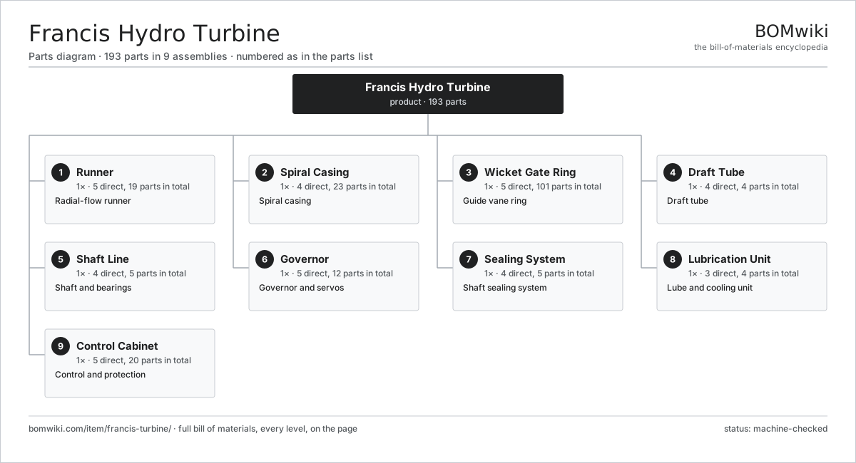
| # | Part | Qty | What it does |
|---|---|---|---|
| 1 | Runner 5 parts | 1× | Radial-flow runner |
| 2 | Spiral Casing 4 parts | 1× | Spiral casing |
| 3 | Wicket Gate Ring 5 parts | 1× | Guide vane ring |
| 4 | Draft Tube 4 parts | 1× | Draft tube |
| 5 | Shaft Line 4 parts | 1× | Shaft and bearings |
| 6 | Governor 5 parts | 1× | Governor and servos |
| 7 | Sealing System 4 parts | 1× | Shaft sealing system |
| 8 | Lubrication Unit 3 parts | 1× | Lube and cooling unit |
| 9 | Control Cabinet 5 parts | 1× | Control and protection |
3D model
No 3D model yet. Have a CAD file of this? Add a 3D model — STL renders right on this page; STEP, FreeCAD, and OpenSCAD sources are welcome too (openly licensed, like all 3D models on BOMwiki).
Build & assembly graph
expand / collapse · shared sub-assemblies converge · links to related products · est. labourTap an assembly to expand/collapse · tap a part to open it · use “Open page” for any node · drag to pan, scroll to zoom.
Bill of materials for Francis Hydro Turbine
9 top-level lines · 56 rows shown · 193 parts total · indented to 3 levels| # | Item / sub-assembly | Part no. | Qty/assy | Ext. qty | Parts | Type |
|---|---|---|---|---|---|---|
| 1 | Runner 5 parts | francis-turbine-runner | 1× | 1 | 19 | assembly |
| 1.1 | Runner Crown | francis-turbine-crown | 1× | 1 | · | part |
| 1.2 | Runner Band | francis-turbine-band | 1× | 1 | · | part |
| 1.3 | Runner Blade | francis-turbine-blade | 15× | 15 | · | part |
| 1.4 | Runner Hub | francis-turbine-runner-hub | 1× | 1 | · | part |
| 1.5 | Fastener Set | fastener-set | 1× | 1 | · | part |
| 2 | Spiral Casing 4 parts | francis-turbine-spiral-case | 1× | 1 | 23 | assembly |
| 2.1 | Volute Shell | francis-turbine-volute-shell | 1× | 1 | · | part |
| 2.2 | Stay Ring | francis-turbine-stay-ring | 1× | 1 | · | part |
| 2.3 | Stay Vane | francis-turbine-stay-vane | 20× | 20 | · | part |
| 2.4 | Inlet Flange | francis-turbine-inlet-flange | 1× | 1 | · | part |
| 3 | Wicket Gate Ring 5 parts | francis-turbine-wicket-gates | 1× | 1 | 101 | assembly |
| 3.1 | Guide Vane | francis-turbine-guide-vane | 20× | 20 | · | part |
| 3.2 | Vane Lever | francis-turbine-vane-arm | 20× | 20 | · | part |
| 3.3 | Operating Ring | francis-turbine-shifting-ring | 1× | 1 | · | part |
| 3.4 | Shear Pin | francis-turbine-shear-pin | 20× | 20 | · | part |
| 3.5 | Vane Bushing | francis-turbine-vane-bushing | 40× | 40 | · | part |
| 4 | Draft Tube 4 parts | francis-turbine-draft-tube | 1× | 1 | 4 | assembly |
| 4.1 | Draft Cone | francis-turbine-draft-cone | 1× | 1 | · | part |
| 4.2 | Draft Elbow | francis-turbine-draft-elbow | 1× | 1 | · | part |
| 4.3 | Draft Liner | francis-turbine-draft-liner | 1× | 1 | · | part |
| 4.4 | Aeration Valve | francis-turbine-aeration-valve | 1× | 1 | · | part |
| 5 | Shaft Line 4 parts | francis-turbine-shaft-line | 1× | 1 | 5 | assembly |
| 5.1 | Main Shaft | francis-turbine-main-shaft | 1× | 1 | · | part |
| 5.2 | Guide Bearing | francis-turbine-guide-bearing | 1× | 1 | · | part |
| 5.3 | Coupling | francis-turbine-coupling | 1× | 1 | · | part |
| 5.4 | Ball Bearing | ball-bearing | 2× | 2 | · | part |
| 6 | Governor 5 parts | francis-turbine-governor | 1× | 1 | 12 | assembly |
| 6.1 | Governor Pump | francis-turbine-gov-pump | 1× | 1 | · | part |
| 6.2 | Accumulator | francis-turbine-gov-accumulator | 1× | 1 | · | part |
| 6.3 | Gate Servomotor | francis-turbine-gate-servo | 2× | 2 | · | part |
| 6.4 | Speed Pickup | francis-turbine-speed-pickup | 1× | 1 | · | part |
| 6.5 | Governor Controller 4 parts | francis-turbine-gov-controller | 1× | 1 | 7 | assembly |
| 6.5.1 | Bare PCB | pcb-bare | 1× | 1 | · | part |
| 6.5.2 | Microcontroller | mcu | 1× | 1 | · | part |
| 6.5.3 | SMD Passive (R/C/L) | smd-passives | 1× | 1 | · | part |
| 6.5.4 | Connector | connector | 4× | 4 | · | part |
| 7 | Sealing System 4 parts | francis-turbine-seals | 1× | 1 | 5 | assembly |
| 7.1 | Wear Ring | francis-turbine-wear-ring | 2× | 2 | · | part |
| 7.2 | Shaft Seal | francis-turbine-shaft-seal | 1× | 1 | · | part |
| 7.3 | Seal Water Unit | francis-turbine-seal-water | 1× | 1 | · | part |
| 7.4 | O-Ring Set | oring-set | 1× | 1 | · | part |
| 8 | Lubrication Unit 3 parts | francis-turbine-cooling | 1× | 1 | 4 | assembly |
| 8.1 | Lube Pump | francis-turbine-lube-pump | 1× | 1 | · | part |
| 8.2 | Oil Cooler | francis-turbine-oil-cooler | 1× | 1 | · | part |
| 8.3 | Oil Filter | francis-turbine-oil-filter | 2× | 2 | · | part |
| 9 | Control Cabinet 5 parts | francis-turbine-controls | 1× | 1 | 20 | assembly |
| 9.1 | Unit PLC 4 parts | francis-turbine-plc | 1× | 1 | 9 | assembly |
| 9.1.1 | Bare PCB | pcb-bare | 1× | 1 | · | part |
| 9.1.2 | Microcontroller | mcu | 1× | 1 | · | part |
| 9.1.3 | SMD Passive (R/C/L) | smd-passives | 1× | 1 | · | part |
| 9.1.4 | Connector | connector | 6× | 6 | · | part |
| 9.2 | Vibration Monitor | francis-turbine-vibration-monitor | 1× | 1 | · | part |
| 9.3 | Power Supply | power-supply | 1× | 1 | · | part |
| 9.4 | Relay | relay | 8× | 8 | · | part |
| 9.5 | Wire Bundle | wire-bundle | 1× | 1 | · | part |
Related products
same domain, ranked by shared parts Concentrated Solar Power Receiver
855 parts · shares 3 with this page
Concentrated Solar Power Receiver
855 parts · shares 3 with this page
 Floating Solar Platform
108 parts · shares 3 with this page
Green Hydrogen Electrolyzer Plant
2,171 parts · shares 3 with this page
Floating Solar Platform
108 parts · shares 3 with this page
Green Hydrogen Electrolyzer Plant
2,171 parts · shares 3 with this page
 Hydro Intake Trash Rack
439 parts · shares 3 with this page
Hydro Intake Trash Rack
439 parts · shares 3 with this page
 Hydropower Penstock
565 parts · shares 3 with this page
Hydropower Penstock
565 parts · shares 3 with this page
Sourcing: possible vendors
Prices, MOQ, and lead times are algorithmic estimates, not quotes, and not claims about these companies. Company mappings are curated by keyword; est. price band $100–$20M. How estimates work| Vendor | HQ | Specialty | MOQ | Lead time |
|---|---|---|---|---|
|
🇩🇰Vestas
vestas.com ↗
|
Aarhus, DK | Wind turbines | 500 units | 12–24 wks |
| firstsolar.com ↗ | Tempe, US | PV modules | 500 units | 12–24 wks |
|
🇨🇳LONGi
longi.com ↗
|
Xi'an, CN | Solar wafers & modules | 500 units | 12–24 wks |
| enphase.com ↗ | Fremont, US | Microinverters & storage | 500 units | 12–24 wks |
|
🇨🇳Sungrow
sungrowpower.com ↗
|
Hefei, CN | Solar inverters & storage | 500 units | 12–24 wks |
978-word article