Pumped Storage Pump-Turbine
ProductOverview
A pumped storage pump-turbine is a single reversible machine that both generates electricity and pumps water uphill, the core of the most widely used form of grid-scale energy storage. When power is cheap or surplus, the unit runs as a pump and lifts water from a lower reservoir to an upper one. When power is needed, the same machine runs in reverse as a turbine and lets the water fall back through it. The arrangement stores energy as the height difference between two reservoirs and returns 75 to 82 percent of it on a round trip. The runner is a Francis design, closely related to the Francis Hydro Turbine, but shaped and sized so it works acceptably in both directions of rotation, which is always a compromise against a machine built for one duty.
Water moves through the Spiral Casing and the Wicket Gate Ring to and from the Reversible Runner, with the Draft Tube connecting the lower reservoir. The Shaft Line links the runner to a motor-generator that the Control and Changeover cabinet switches between modes. Starting in pump mode needs the Air Depression System system, the Governor controls flow, and the Lubrication Unit unit feeds the bearings.
The reversible runner
The Reversible Runner is the design heart of the machine and its hardest compromise. In turbine mode water flows inward through the blades and the runner takes torque from it. In pump mode the rotation reverses, the runner adds energy to the water, and the flow goes outward. A blade profile that is ideal for one of these is poor for the other, so the Runner Blade shape between the Runner Crown and Runner Band is a balance that gives good but not peak efficiency each way. Pumping needs more head than generating gives back at the same flow, so the runner usually has more blades and a different inlet angle than a pure turbine runner. Renewable Wear Ring pairs set the leakage clearance, and the runner locks to the shaft through the Runner Hub. Pumping also raises the cavitation risk, which is why these runners are set deep below the lower reservoir level.
Water passages and gates
The Spiral Casing is built heavier than a turbine volute because it sees the full penstock head in both directions. Its Volute Shell distributes flow around a Stay Ring with fixed Stay Vane members, fed by the Penstock Flange. The Wicket Gate Ring ring meters flow in both modes and, importantly, can shut tight: the pivoting Guide Vane members close through their Vane Lever links and the Operating Ring to seal the runner while the unit spins up in air before pumping. They turn in Vane Bushing supports with a Shear Pin for jam protection. The Draft Tube, with its Draft Cone and Draft Elbow lined by a Draft Liner, serves as the turbine outlet and the pump intake.
Starting and changing mode
A pump cannot start against a full column of water, so the Air Depression System system blows the runner clear first. A Air Compressor charges a Air Receiver, and on a pump start the Depression Valve elements admit air that pushes the water down out of the runner so the motor can spin the empty runner up to speed in air with little load. Once at speed the gates open, water refills the runner, and pumping begins. Changing from generating to pumping means stopping the unit, reversing its rotation, depressing the water, and restarting, which takes several minutes and is sequenced by the Changeover Logic with its interlocks. This mode change time is the main operational limit, and it is why some newer plants use variable-speed drives to widen the operating range.
Shaft line, governing, and auxiliaries
The Shaft Line is sized for the demands of both duties. Its forged Main Shaft runs in Guide Bearing sleeves, and a heavy Thrust Bearing carries the large axial load that pumping creates, with a Shaft Seal at the head cover and a Coupling to the motor-generator. The Governor drives the guide vanes through Gate Servomotor cylinders fed by a Governor Pump and Accumulator, with a Speed Pickup and a Governor Controller closing the loop. The Lubrication Unit unit circulates filtered oil through the Oil Cooler from its Oil Reservoir, and the Control and Changeover cabinet sequences everything through its Unit PLC under a Vibration Monitor.
Where pump-turbines fit
Pumped storage is by far the largest store of grid energy in service, and the reversible pump-turbine is the machine that makes it economic, because one unit and one waterway serve both duties instead of separate pumps and turbines. The head range from about 100 to 700 metres overlaps the Francis Hydro Turbine band, and the same site arithmetic that favours a Francis machine for generation favours its reversible cousin for storage. The technology absorbs surplus output from inflexible plants and from variable wind and solar, then returns it at peak, smoothing a grid that carries more intermittent generation each year. Its limits are geographic, since it needs two reservoirs with a useful height between them, and operational, since the mode change is not instant. Within those limits it remains the cheapest way to store large amounts of energy for hours at a time.
Pumped Storage Pump-Turbine parts and their functions
9 top-level parts · 203 parts in total · full bill of materials below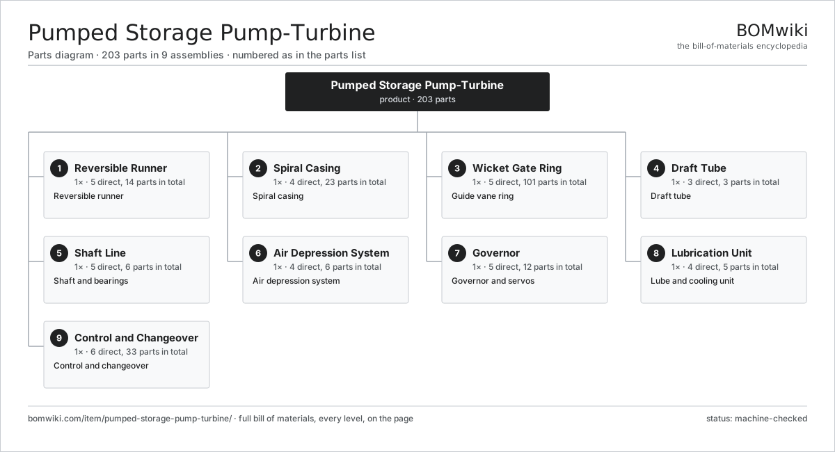
| # | Part | Qty | What it does |
|---|---|---|---|
| 1 | Reversible Runner 5 parts | 1× | Reversible runner |
| 2 | Spiral Casing 4 parts | 1× | Spiral casing |
| 3 | Wicket Gate Ring 5 parts | 1× | Guide vane ring |
| 4 | Draft Tube 3 parts | 1× | Draft tube |
| 5 | Shaft Line 5 parts | 1× | Shaft and bearings |
| 6 | Air Depression System 4 parts | 1× | Air depression system |
| 7 | Governor 5 parts | 1× | Governor and servos |
| 8 | Lubrication Unit 4 parts | 1× | Lube and cooling unit |
| 9 | Control and Changeover 6 parts | 1× | Control and changeover |
3D model
No 3D model yet. Have a CAD file of this? Add a 3D model — STL renders right on this page; STEP, FreeCAD, and OpenSCAD sources are welcome too (openly licensed, like all 3D models on BOMwiki).
Build & assembly graph
expand / collapse · shared sub-assemblies converge · links to related products · est. labourTap an assembly to expand/collapse · tap a part to open it · use “Open page” for any node · drag to pan, scroll to zoom.
Bill of materials for Pumped Storage Pump-Turbine
9 top-level lines · 61 rows shown · 203 parts total · indented to 3 levels| # | Item / sub-assembly | Part no. | Qty/assy | Ext. qty | Parts | Type |
|---|---|---|---|---|---|---|
| 1 | Reversible Runner 5 parts | pumped-storage-pump-turbine-runner | 1× | 1 | 14 | assembly |
| 1.1 | Runner Crown | pumped-storage-pump-turbine-crown | 1× | 1 | · | part |
| 1.2 | Runner Band | pumped-storage-pump-turbine-band | 1× | 1 | · | part |
| 1.3 | Runner Blade | pumped-storage-pump-turbine-blade | 9× | 9 | · | part |
| 1.4 | Wear Ring | pumped-storage-pump-turbine-wear-ring | 2× | 2 | · | part |
| 1.5 | Runner Hub | pumped-storage-pump-turbine-runner-hub | 1× | 1 | · | part |
| 2 | Spiral Casing 4 parts | pumped-storage-pump-turbine-spiral-case | 1× | 1 | 23 | assembly |
| 2.1 | Volute Shell | pumped-storage-pump-turbine-volute-shell | 1× | 1 | · | part |
| 2.2 | Stay Ring | pumped-storage-pump-turbine-stay-ring | 1× | 1 | · | part |
| 2.3 | Stay Vane | pumped-storage-pump-turbine-stay-vane | 20× | 20 | · | part |
| 2.4 | Penstock Flange | pumped-storage-pump-turbine-inlet-flange | 1× | 1 | · | part |
| 3 | Wicket Gate Ring 5 parts | pumped-storage-pump-turbine-wicket-gates | 1× | 1 | 101 | assembly |
| 3.1 | Guide Vane | pumped-storage-pump-turbine-guide-vane | 20× | 20 | · | part |
| 3.2 | Vane Lever | pumped-storage-pump-turbine-vane-arm | 20× | 20 | · | part |
| 3.3 | Operating Ring | pumped-storage-pump-turbine-shifting-ring | 1× | 1 | · | part |
| 3.4 | Vane Bushing | pumped-storage-pump-turbine-vane-bushing | 40× | 40 | · | part |
| 3.5 | Shear Pin | pumped-storage-pump-turbine-shear-pin | 20× | 20 | · | part |
| 4 | Draft Tube 3 parts | pumped-storage-pump-turbine-draft-tube | 1× | 1 | 3 | assembly |
| 4.1 | Draft Cone | pumped-storage-pump-turbine-draft-cone | 1× | 1 | · | part |
| 4.2 | Draft Elbow | pumped-storage-pump-turbine-draft-elbow | 1× | 1 | · | part |
| 4.3 | Draft Liner | pumped-storage-pump-turbine-draft-liner | 1× | 1 | · | part |
| 5 | Shaft Line 5 parts | pumped-storage-pump-turbine-shaft-line | 1× | 1 | 6 | assembly |
| 5.1 | Main Shaft | pumped-storage-pump-turbine-main-shaft | 1× | 1 | · | part |
| 5.2 | Guide Bearing | pumped-storage-pump-turbine-guide-bearing | 2× | 2 | · | part |
| 5.3 | Thrust Bearing | pumped-storage-pump-turbine-thrust-bearing | 1× | 1 | · | part |
| 5.4 | Shaft Seal | pumped-storage-pump-turbine-shaft-seal | 1× | 1 | · | part |
| 5.5 | Coupling | pumped-storage-pump-turbine-coupling | 1× | 1 | · | part |
| 6 | Air Depression System 4 parts | pumped-storage-pump-turbine-aeration | 1× | 1 | 6 | assembly |
| 6.1 | Air Compressor | pumped-storage-pump-turbine-air-compressor | 1× | 1 | · | part |
| 6.2 | Air Receiver | pumped-storage-pump-turbine-air-receiver | 1× | 1 | · | part |
| 6.3 | Depression Valve | pumped-storage-pump-turbine-depression-valve | 2× | 2 | · | part |
| 6.4 | Pressure Sensor | pressure-sensor | 2× | 2 | · | part |
| 7 | Governor 5 parts | pumped-storage-pump-turbine-governor | 1× | 1 | 12 | assembly |
| 7.1 | Governor Pump | pumped-storage-pump-turbine-gov-pump | 1× | 1 | · | part |
| 7.2 | Accumulator | pumped-storage-pump-turbine-gov-accumulator | 1× | 1 | · | part |
| 7.3 | Gate Servomotor | pumped-storage-pump-turbine-gate-servo | 2× | 2 | · | part |
| 7.4 | Speed Pickup | pumped-storage-pump-turbine-speed-pickup | 1× | 1 | · | part |
| 7.5 | Governor Controller 4 parts | pumped-storage-pump-turbine-gov-controller | 1× | 1 | 7 | assembly |
| 7.5.1 | Bare PCB | pcb-bare | 1× | 1 | · | part |
| 7.5.2 | Microcontroller | mcu | 1× | 1 | · | part |
| 7.5.3 | SMD Passive (R/C/L) | smd-passives | 1× | 1 | · | part |
| 7.5.4 | Connector | connector | 4× | 4 | · | part |
| 8 | Lubrication Unit 4 parts | pumped-storage-pump-turbine-cooling | 1× | 1 | 5 | assembly |
| 8.1 | Lube Pump | pumped-storage-pump-turbine-lube-pump | 1× | 1 | · | part |
| 8.2 | Oil Cooler | pumped-storage-pump-turbine-oil-cooler | 1× | 1 | · | part |
| 8.3 | Oil Filter | pumped-storage-pump-turbine-oil-filter | 2× | 2 | · | part |
| 8.4 | Oil Reservoir | pumped-storage-pump-turbine-oil-tank | 1× | 1 | · | part |
| 9 | Control and Changeover 6 parts | pumped-storage-pump-turbine-controls | 1× | 1 | 33 | assembly |
| 9.1 | Unit PLC 4 parts | pumped-storage-pump-turbine-plc | 1× | 1 | 9 | assembly |
| 9.1.1 | Bare PCB | pcb-bare | 1× | 1 | · | part |
| 9.1.2 | Microcontroller | mcu | 1× | 1 | · | part |
| 9.1.3 | SMD Passive (R/C/L) | smd-passives | 1× | 1 | · | part |
| 9.1.4 | Connector | connector | 6× | 6 | · | part |
| 9.2 | Changeover Logic 3 parts | pumped-storage-pump-turbine-changeover-logic | 1× | 1 | 11 | assembly |
| 9.2.1 | Bare PCB | pcb-bare | 1× | 1 | · | part |
| 9.2.2 | Relay | relay | 6× | 6 | · | part |
| 9.2.3 | Connector | connector | 4× | 4 | · | part |
| 9.3 | Vibration Monitor | pumped-storage-pump-turbine-vibration-monitor | 1× | 1 | · | part |
| 9.4 | Power Supply | power-supply | 1× | 1 | · | part |
| 9.5 | Relay | relay | 10× | 10 | · | part |
| 9.6 | Wire Bundle | wire-bundle | 1× | 1 | · | part |
Related products
same domain, ranked by shared parts Battery Energy Storage System
17,429 parts · shares 2 with this page
Biogas Upgrading Unit
110 parts · shares 2 with this page
Battery Energy Storage System
17,429 parts · shares 2 with this page
Biogas Upgrading Unit
110 parts · shares 2 with this page
 Biomass Pellet Plant
404 parts · shares 2 with this page
Biomass Pellet Plant
404 parts · shares 2 with this page
 Concentrated Solar Power Receiver
855 parts · shares 2 with this page
Concentrated Solar Power Receiver
855 parts · shares 2 with this page
 Floating Offshore Wind Turbine
608 parts · shares 2 with this page
Green Hydrogen Electrolyzer Plant
2,171 parts · shares 2 with this page
Floating Offshore Wind Turbine
608 parts · shares 2 with this page
Green Hydrogen Electrolyzer Plant
2,171 parts · shares 2 with this page
Sourcing: possible vendors
Prices, MOQ, and lead times are algorithmic estimates, not quotes, and not claims about these companies. Company mappings are curated by keyword; est. price band $100–$20M. How estimates work| Vendor | HQ | Specialty | MOQ | Lead time |
|---|---|---|---|---|
|
🇩🇰Vestas
vestas.com ↗
|
Aarhus, DK | Wind turbines | 500 units | 12–24 wks |
| firstsolar.com ↗ | Tempe, US | PV modules | 500 units | 12–24 wks |
|
🇨🇳LONGi
longi.com ↗
|
Xi'an, CN | Solar wafers & modules | 500 units | 12–24 wks |
| enphase.com ↗ | Fremont, US | Microinverters & storage | 500 units | 12–24 wks |
|
🇨🇳Sungrow
sungrowpower.com ↗
|
Hefei, CN | Solar inverters & storage | 500 units | 12–24 wks |
1,074-word article