Wind Turbine Nacelle
ProductOverview
The nacelle is the housing mounted on top of a wind turbine tower that holds the drivetrain and the equipment converting rotor motion into grid electricity. On a geared horizontal-axis machine in the 2-4 MW class, the rotor spins slowly, between 10 and 20 rpm, while the generator needs roughly 1000-1800 rpm to make power at usable voltage. The nacelle bridges that gap with a step-up gearbox and converts the resulting mechanical power with an electrical generator and a power converter. It also carries everything needed to keep the machine pointed into the wind, lubricated, cooled, braked and monitored over a service life of 20-25 years at the top of an 80-120 m tower.
A typical nacelle masses 60-110 tonnes including the rotor hub. The Bedplate and Cover is a ductile iron casting bolted to the yaw bearing, and it carries the Wind Turbine Main Shaft and Bearings, the Step-Up Gearbox and the Doubly-Fed Induction Generator in a line. A fiberglass cover keeps weather out and houses the met sensors on its roof.
Drivetrain and how it works
Wind turns the three-blade rotor, which bolts to the main shaft. The Wind Turbine Main Shaft and Bearings is a forged steel low-speed shaft supported on two large spherical roller Main Bearing units that carry both the weight of the rotor and the axial thrust of the wind. These main bearings see very high loads at low speed, so they are greased rather than oil-fed and sealed with Oil Seal labyrinths. The shaft delivers torque into the gearbox through a shrink disc, and a pin-type rotor lock lets technicians immobilize the rotor before climbing out to the hub.
Power flows from the shaft through the gearbox to the generator, then through the converter and transformer to the grid. The controller sets blade pitch and generator torque to hold rated power once the wind passes about 12-14 m/s, and feathers the blades and applies the brake above the 25 m/s cut-out speed.
Gearbox
The Step-Up Gearbox raises rotor speed by roughly 100:1 in three stages. The first stage is a planetary set: a Planet Carrier driven by the main shaft carries three planet gears that run between the sun gear and a fixed Ring Gear bolted to the Gearbox Housing. Splitting load across three planets keeps the first stage compact for the very high input torque. Two further helical stages, built from Helical Gear Pair meshes, step the speed up to the High-Speed Shaft turning at 1000-1800 rpm. The gear shafts ride on tapered and cylindrical Ball Bearing supports, and the whole box is fed by a filtered, forced oil loop that holds oil between 40 and 65 °C. The gearbox is the most heavily stressed and most failure-prone item in the nacelle, so its bearings and gear teeth are watched closely by the condition monitoring system.
Generator and converter
The reference design uses a Doubly-Fed Induction Generator, a doubly-fed induction generator (DFIG). Its Stator Assembly connects straight to the grid side at 690 V, while its wound Rotor Assembly is fed through a Slip Ring Unit from a back-to-back IGBT Power Converter. Because the converter only handles the slip power, it is sized to roughly 30 percent of the machine rating rather than the full output, which lowers cost and losses compared with a full-converter design. The converter lets the generator run at variable speed across a band around synchronous speed, so the rotor can track the wind for best aerodynamic efficiency while the stator still delivers grid-frequency power. An encoder reports generator speed and angle to the converter control. Output is conditioned by Switchgear and, where the transformer sits in the nacelle, stepped up to 33 kV before it travels down the tower.
Yaw and braking
The Yaw System keeps the rotor facing the wind. A large slewing Yaw Bearing joins the nacelle to the tower top, and four to eight geared Servo Motor drives mesh with its toothed ring to rotate the whole nacelle. A wind vane on the cover measures the yaw error, and the controller turns the nacelle slowly, at a fraction of a degree per second, to null it; hydraulic caliper yaw brakes and friction pads then hold the azimuth against wind gusts. Separately, the Mechanical Brake System is a spring-applied, hydraulically released disc brake on the high-speed shaft. Springs clamp the caliper if hydraulic pressure is lost, so the brake fails safe and stops the rotor for parking, faults or service. The Hydraulic Power Unit supplies pressure to the brakes and yaw through an accumulator that allows fast actuation, with Pressure Sensor feedback confirming each circuit.
Control, maintenance and variants
The Wind Turbine Control and Condition Monitoring system ties the subsystems together. The turbine controller reads two anemometers, the wind vane and a set of Vibration Sensor accelerometers on the bearings and gearbox, then commands pitch, torque, yaw and braking. The vibration data drives condition monitoring that flags gear and bearing wear before failure, which matters because a gearbox change-out needs a large crane and days of downtime. Routine maintenance covers oil sampling and changes, filter swaps, brake pad checks, bolt torque audits and bearing greasing. The Wind Turbine Lubrication and Cooling keeps oil and windings in range, using an oil heater with Heating Element units to raise viscosity for cold starts in winter sites.
Direct-drive turbines are the main variant. They delete the gearbox and couple the rotor to a large, slow permanent-magnet generator turning at rotor speed, which removes the most failure-prone component at the cost of a much heavier and more expensive generator. Medium-speed hybrids keep a single planetary stage and a smaller permanent-magnet machine as a compromise between the geared DFIG layout described here and a full direct-drive design.
Wind Turbine Nacelle parts and their functions
10 top-level parts · 287 parts in total · full bill of materials below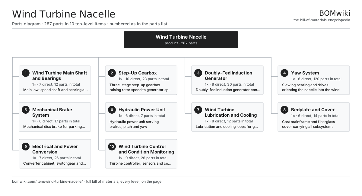
| # | Part | Qty | What it does |
|---|---|---|---|
| 1 | Wind Turbine Main Shaft and Bearings 7 parts | 1× | Main low-speed shaft and bearing assembly transmitting rotor torque |
| 2 | Step-Up Gearbox 10 parts | 1× | Three-stage step-up gearbox raising rotor speed to generator speed |
| 3 | Doubly-Fed Induction Generator 8 parts | 1× | Doubly-fed induction generator converting shaft power to electricity |
| 4 | Yaw System 6 parts | 1× | Slewing bearing and drives orienting the nacelle into the wind |
| 5 | Mechanical Brake System 6 parts | 1× | Mechanical disc brake for parking and emergency stop |
| 6 | Hydraulic Power Unit 6 parts | 1× | Hydraulic power unit serving brakes, pitch and yaw |
| 7 | Wind Turbine Lubrication and Cooling 8 parts | 1× | Lubrication and cooling loops for gearbox and generator |
| 8 | Bedplate and Cover 6 parts | 1× | Cast mainframe and fiberglass cover carrying all subsystems |
| 9 | Electrical and Power Conversion 7 parts | 1× | Converter cabinet, switchgear and nacelle wiring |
| 10 | Wind Turbine Control and Condition Monitoring 9 parts | 1× | Turbine controller, sensors and condition monitoring |
3D model
No 3D model yet. Have a CAD file of this? Add a 3D model. STL renders right on this page; STEP, FreeCAD, and OpenSCAD sources are welcome too (openly licensed, like all 3D models on BOMwiki).
Build & assembly graph
expand / collapse · shared sub-assemblies converge · links to related products · est. labourTap an assembly to expand/collapse · tap a part to open it · use “Open page” for any node · drag to pan, scroll to zoom.
Bill of materials for Wind Turbine Nacelle
10 top-level lines · 94 rows shown · 287 parts total · indented to 3 levels| # | Item / sub-assembly | Part no. | Qty/assy | Ext. qty | Parts | Type |
|---|---|---|---|---|---|---|
| 1 | Wind Turbine Main Shaft and Bearings 7 parts | wind-turbine-nacelle-rotor-shaft | 1× | 1 | 12 | assembly |
| 1.1 | Main Shaft | wind-turbine-nacelle-main-shaft | 1× | 1 | · | part |
| 1.2 | Main Bearing | wind-turbine-nacelle-main-bearing | 2× | 2 | · | part |
| 1.3 | Main Bearing Housing | wind-turbine-nacelle-bearing-housing | 2× | 2 | · | part |
| 1.4 | Shrink Disc | wind-turbine-nacelle-shrink-disc | 1× | 1 | · | part |
| 1.5 | Oil Seal | oil-seal | 4× | 4 | · | part |
| 1.6 | Rotor Lock | wind-turbine-nacelle-rotor-lock | 1× | 1 | · | part |
| 1.7 | Fastener Set | fastener-set | 1× | 1 | · | part |
| 2 | Step-Up Gearbox 10 parts | wind-turbine-nacelle-gearbox | 1× | 1 | 23 | assembly |
| 2.1 | Gearbox Housing | gearbox-housing | 1× | 1 | · | part |
| 2.2 | Planet Carrier | wind-turbine-nacelle-planet-carrier | 1× | 1 | · | part |
| 2.3 | Ring Gear | wind-turbine-nacelle-ring-gear | 1× | 1 | · | part |
| 2.4 | Helical Gear Pair | gear-pair | 5× | 5 | · | part |
| 2.5 | High-Speed Shaft | wind-turbine-nacelle-hs-shaft | 1× | 1 | · | part |
| 2.6 | Ball Bearing | ball-bearing | 8× | 8 | · | part |
| 2.7 | Oil Seal | oil-seal | 3× | 3 | · | part |
| 2.8 | O-Ring Set | oring-set | 1× | 1 | · | part |
| 2.9 | Gearbox Oil Filter | wind-turbine-nacelle-oil-filter | 1× | 1 | · | part |
| 2.10 | Fastener Set | fastener-set | 1× | 1 | · | part |
| 3 | Doubly-Fed Induction Generator 8 parts | wind-turbine-nacelle-generator | 1× | 1 | 30 | assembly |
| 3.1 | Stator Assembly 3 parts | stator-assembly | 1× | 1 | 3 | assembly |
| 3.1.1 | Stator Core (laminations) | stator-core | 1× | 1 | · | part |
| 3.1.2 | Copper Winding | copper-winding | 1× | 1 | · | part |
| 3.1.3 | Slot Insulation | stator-insulation | 1× | 1 | · | part |
| 3.2 | Rotor Assembly 4 parts | rotor-assembly | 1× | 1 | 19 | assembly |
| 3.2.1 | Rotor Shaft | rotor-shaft | 1× | 1 | · | part |
| 3.2.2 | Rotor Core | rotor-core | 1× | 1 | · | part |
| 3.2.3 | Neodymium Magnet | neodymium-magnet | 16× | 16 | · | part |
| 3.2.4 | Ball Bearing | ball-bearing | 1× | 1 | · | part |
| 3.3 | Slip Ring Unit | wind-turbine-nacelle-slip-ring | 1× | 1 | · | part |
| 3.4 | Ball Bearing | ball-bearing | 2× | 2 | · | part |
| 3.5 | Speed Encoder | wind-turbine-nacelle-encoder | 1× | 1 | · | part |
| 3.6 | Generator Cooling Fan | wind-turbine-nacelle-generator-fan | 1× | 1 | · | part |
| 3.7 | Oil Seal | oil-seal | 2× | 2 | · | part |
| 3.8 | Fastener Set | fastener-set | 1× | 1 | · | part |
| 4 | Yaw System 6 parts | wind-turbine-nacelle-yaw-system | 1× | 1 | 120 | assembly |
| 4.1 | Yaw Bearing | wind-turbine-nacelle-yaw-bearing | 1× | 1 | · | part |
| 4.2 | Yaw Drive | wind-turbine-nacelle-yaw-drive | 4× | 4 | · | part |
| 4.3 | Servo Motor 4 parts | servo-motor | 4× | 4 | 24 | assembly |
| 4.3.1 | Stator Assembly 3 parts + deeper › | stator-assembly | 1× | 4 | 3 | assembly |
| 4.3.2 | Rotor Assembly 4 parts + deeper › | rotor-assembly | 1× | 4 | 19 | assembly |
| 4.3.3 | Encoder | encoder | 1× | 4 | · | part |
| 4.3.4 | Motor Housing | motor-housing | 1× | 4 | · | part |
| 4.4 | Yaw Brake Caliper | wind-turbine-nacelle-yaw-brake | 6× | 6 | · | part |
| 4.5 | Yaw Sliding Pad | wind-turbine-nacelle-yaw-pad | 12× | 12 | · | part |
| 4.6 | Fastener Set | fastener-set | 1× | 1 | · | part |
| 5 | Mechanical Brake System 6 parts | wind-turbine-nacelle-brake-system | 1× | 1 | 17 | assembly |
| 5.1 | Brake Disc | wind-turbine-nacelle-brake-disc | 1× | 1 | · | part |
| 5.2 | Brake Caliper | wind-turbine-nacelle-brake-caliper | 2× | 2 | · | part |
| 5.3 | Brake Pad | wind-turbine-nacelle-brake-pad | 4× | 4 | · | part |
| 5.4 | Coil Spring | coil-spring | 8× | 8 | · | part |
| 5.5 | Pressure Sensor | pressure-sensor | 1× | 1 | · | part |
| 5.6 | Fastener Set | fastener-set | 1× | 1 | · | part |
| 6 | Hydraulic Power Unit 6 parts | wind-turbine-nacelle-hydraulic-unit | 1× | 1 | 7 | assembly |
| 6.1 | Hydraulic Pump | wind-turbine-nacelle-hyd-pump | 1× | 1 | · | part |
| 6.2 | Hydraulic Reservoir | wind-turbine-nacelle-hyd-tank | 1× | 1 | · | part |
| 6.3 | Hydraulic Accumulator | wind-turbine-nacelle-accumulator | 1× | 1 | · | part |
| 6.4 | Valve Block | wind-turbine-nacelle-valve-block | 1× | 1 | · | part |
| 6.5 | Pressure Sensor | pressure-sensor | 2× | 2 | · | part |
| 6.6 | O-Ring Set | oring-set | 1× | 1 | · | part |
| 7 | Wind Turbine Lubrication and Cooling 8 parts | wind-turbine-nacelle-cooling-system | 1× | 1 | 12 | assembly |
| 7.1 | Lube Oil Pump | wind-turbine-nacelle-oil-pump | 1× | 1 | · | part |
| 7.2 | Oil Cooler | wind-turbine-nacelle-oil-cooler | 1× | 1 | · | part |
| 7.3 | Coolant Pump | wind-turbine-nacelle-coolant-pump | 1× | 1 | · | part |
| 7.4 | Radiator | wind-turbine-nacelle-radiator | 1× | 1 | · | part |
| 7.5 | Oil Heater | wind-turbine-nacelle-oil-heater | 1× | 1 | · | part |
| 7.6 | Heating Element | heating-element | 2× | 2 | · | part |
| 7.7 | Temperature Sensor | wind-turbine-nacelle-temp-sensor | 4× | 4 | · | part |
| 7.8 | O-Ring Set | oring-set | 1× | 1 | · | part |
| 8 | Bedplate and Cover 6 parts | wind-turbine-nacelle-bedplate | 1× | 1 | 14 | assembly |
| 8.1 | Mainframe Casting | wind-turbine-nacelle-mainframe | 1× | 1 | · | part |
| 8.2 | Sheet Metal Panel | sheet-panel | 6× | 6 | · | part |
| 8.3 | Service Hatch | wind-turbine-nacelle-service-hatch | 1× | 1 | · | part |
| 8.4 | Service Walkway | wind-turbine-nacelle-walkway | 1× | 1 | · | part |
| 8.5 | Vibration Mount | wind-turbine-nacelle-vibration-mount | 4× | 4 | · | part |
| 8.6 | Fastener Set | fastener-set | 1× | 1 | · | part |
| 9 | Electrical and Power Conversion 7 parts | wind-turbine-nacelle-electrical | 1× | 1 | 26 | assembly |
| 9.1 | Power Converter | wind-turbine-nacelle-converter | 1× | 1 | · | part |
| 9.2 | Switchgear | wind-turbine-nacelle-switchgear | 1× | 1 | · | part |
| 9.3 | Step-Up Transformer | wind-turbine-nacelle-transformer | 1× | 1 | · | part |
| 9.4 | Power Supply | power-supply | 1× | 1 | · | part |
| 9.5 | Wire Bundle | wire-bundle | 4× | 4 | · | part |
| 9.6 | Connector | connector | 12× | 12 | · | part |
| 9.7 | Relay | relay | 6× | 6 | · | part |
| 10 | Wind Turbine Control and Condition Monitoring 9 parts | wind-turbine-nacelle-control | 1× | 1 | 26 | assembly |
| 10.1 | Turbine Controller | wind-turbine-nacelle-controller | 1× | 1 | · | part |
| 10.2 | Microcontroller | mcu | 2× | 2 | · | part |
| 10.3 | Bare PCB | pcb-bare | 3× | 3 | · | part |
| 10.4 | SMD Passive (R/C/L) | smd-passives | 4× | 4 | · | part |
| 10.5 | Anemometer | wind-turbine-nacelle-anemometer | 2× | 2 | · | part |
| 10.6 | Wind Vane | wind-turbine-nacelle-wind-vane | 1× | 1 | · | part |
| 10.7 | Vibration Sensor | wind-turbine-nacelle-vibration-sensor | 4× | 4 | · | part |
| 10.8 | LCD Panel | lcd-panel | 1× | 1 | · | part |
| 10.9 | Connector | connector | 8× | 8 | · | part |
Something wrong in this list? Report a problem with this BOM.
Used in 1 assembly
Related products
same domain, ranked by shared parts Wind Turbine
28,312 parts · shares 72 with this page
Green Hydrogen Electrolyzer Plant
2,171 parts · shares 20 with this page
 Biomass Pellet Plant
404 parts · shares 18 with this page
 Concentrated Solar Power Receiver
855 parts · shares 19 with this page
 Floating Offshore Wind Turbine
608 parts · shares 18 with this page
Utility-Scale Solar Inverter
204 parts · shares 19 with this page
Sourcing: possible vendors
Browse the supplier directory → Prices, MOQ, and lead times are algorithmic estimates, not quotes, and not claims about these companies. Company mappings are curated by keyword; est. price band $100–$20M. How estimates work| Vendor | HQ | Specialty | MOQ | Lead time |
|---|---|---|---|---|
|
🇩🇰Vestas
vestas.com ↗
|
Aarhus, DK | Wind turbines | 500 units | 12–24 wks |
| firstsolar.com ↗ | Tempe, US | PV modules | 500 units | 12–24 wks |
|
🇨🇳LONGi
longi.com ↗
|
Xi'an, CN | Solar wafers & modules | 500 units | 12–24 wks |
| enphase.com ↗ | Fremont, US | Microinverters & storage | 500 units | 12–24 wks |
|
🇨🇳Sungrow
sungrowpower.com ↗
|
Hefei, CN | Solar inverters & storage | 500 units | 12–24 wks |
1,024-word article