Wind Turbine Blade
ProductOverview
A wind turbine blade is a long composite aerofoil that converts the energy in moving air into a torque on the rotor shaft. A modern utility blade is between 60 and 90 metres long and weighs from 12 to 35 tonnes, yet it must be light enough to spin and stiff enough not to strike the tower in a gust. The blade does this by being a hollow beam: two thin aerodynamic shells give it shape, and an internal spar carries the load. The section twists and tapers from a thick circular root, where it bolts to the hub, to a thin sharp tip, so each part of the span meets the wind at an efficient angle.
The blade is built from a small number of large subassemblies. The Shell Set forms the outer aerofoil, the Wind Turbine Blade Structural Spar is the beam inside it, and the Wind Turbine Blade Root Joint transfers everything into the hub. The Bond System glues these pieces into one body, the Wind Turbine Blade Lightning Protection handles the outboard end and lightning, the Wind Turbine Blade Surface Protection protects and tunes the exterior, and the Sensor System reports load and condition back to the turbine controller.
Shells and the aerofoil
The aerodynamic surface is made of two half-shells: the Suction-Side Shell on top and the Pressure-Side Shell underneath. Each is a sandwich laminate, two skins of Glass Reinforcement Fabric with a lightweight core between them, which gives a stiff panel for very little weight. The core is the Sandwich Core Kit, a mix of End-Grain Balsa Core in the highly loaded zones and PET Structural Foam elsewhere. The Leading-Edge Reinforcement gets extra plies because the air stagnates there and erosion is worst, while the thin Trailing-Edge Close-Out needs a careful close-out so the two shells meet cleanly. Shells are made by vacuum infusion: dry fabric and core are laid into a heated mold, sealed under a vacuum bag, and epoxy is drawn through the stack before it cures.
Spar and load path
The shells alone could not carry the bending load, so the real strength comes from the Wind Turbine Blade Structural Spar, which works like an I-beam. The flanges of that beam are the Spar Cap members, thick stacks of Unidirectional Laminate running almost the full length of the blade, one bonded into each shell. The web of the beam is a pair of Shear Web panels standing between the caps. Each web is itself a sandwich with a Shear-Web Core to stop it buckling, and it meets the caps through wide Bond Flange feet that spread the joint load. When the wind pushes the blade, the spar caps go into tension and compression while the webs carry the shear, exactly as the flanges and web of a steel beam would.
Root joint
All of the blade load funnels into the Wind Turbine Blade Root Joint, the thick circular base that bolts to the pitch bearing on the hub. The root cannot simply be bolted through composite, so a ring of Root Bushing Insert steel bushings is cured into the Root-End Laminate. Each bushing accepts a Root Stud, and the studs pull the blade tight against the Root Flange Ring using the Fastener Set nuts and washers. A large blade may carry 80 to 120 of these studs around the bolt circle. This joint is the most heavily loaded interface on the blade because the entire bending moment of a 90-metre lever arm is reacted in a short steel-to-composite transition.
Bonding and assembly
A blade leaves the mold as separate parts that must be joined into a single sealed body, which is the job of the Bond System. Workers apply Structural Bond Paste, a toughened epoxy adhesive, along several long Bond Line seams: the leading edge, the trailing edge, and where the webs meet the shells. The mold halves close over O-Ring Set seals, and the bond paste cures under pressure. These glue lines are the most safety-critical step in the whole process, since a void or a starved bond can grow into a crack over millions of load cycles, so each seam is dimensioned for a controlled glue gap and inspected.
Tip, surface, and sensing
The Wind Turbine Blade Lightning Protection finishes the outboard end with a Tip Cap and protects the blade from lightning. Because the composite cannot carry strike current, several Lightning Receptor discs sit flush in the surface and connect to a Down-Conductor Cable copper cable, held by a Conductor Anchor Bracket anchor, that carries the current safely to the root. The Wind Turbine Blade Surface Protection seals and tunes the exterior: a Gelcoat Finish outer finish resists UV, a Leading-Edge Protection film fights rain erosion at tip speeds near 90 metres per second, and bonded-on devices such as the Vortex Generator, the Serrated Trailing Edge, and root Spoiler Panel panels shape the airflow and cut noise. Finally the Sensor System embeds a Strain Sensor set at the root, Blade Accelerometer units along the span, and an Ice-Detection Sensor, all read by a Sensor Interface Board over an internal Wire Bundle, so the turbine controller can balance load between blades, detect ice, and watch for damage over a design life of 20 to 25 years.
Wind Turbine Blade parts and their functions
7 top-level parts · 384 parts in total · full bill of materials below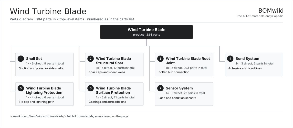
| # | Part | Qty | What it does |
|---|---|---|---|
| 1 | Shell Set 6 parts | 1× | Suction and pressure side shells |
| 2 | Wind Turbine Blade Structural Spar 5 parts | 1× | Spar caps and shear webs |
| 3 | Wind Turbine Blade Root Joint 5 parts | 1× | Bolted hub connection |
| 4 | Bond System 3 parts | 1× | Adhesive and bond lines |
| 5 | Wind Turbine Blade Lightning Protection 4 parts | 1× | Tip cap and lightning path |
| 6 | Wind Turbine Blade Surface Protection 5 parts | 1× | Coatings and aero add-ons |
| 7 | Sensor System 5 parts | 1× | Load and condition sensors |
3D model
No 3D model yet. Have a CAD file of this? Add a 3D model. STL renders right on this page; STEP, FreeCAD, and OpenSCAD sources are welcome too (openly licensed, like all 3D models on BOMwiki).
Build & assembly graph
expand / collapse · shared sub-assemblies converge · links to related products · est. labourTap an assembly to expand/collapse · tap a part to open it · use “Open page” for any node · drag to pan, scroll to zoom.
Bill of materials for Wind Turbine Blade
7 top-level lines · 49 rows shown · 384 parts total · indented to 3 levels| # | Item / sub-assembly | Part no. | Qty/assy | Ext. qty | Parts | Type |
|---|---|---|---|---|---|---|
| 1 | Shell Set 6 parts | wtb-shell-set | 1× | 1 | 9 | assembly |
| 1.1 | Suction-Side Shell | wtb-suction-shell | 1× | 1 | · | part |
| 1.2 | Pressure-Side Shell | wtb-pressure-shell | 1× | 1 | · | part |
| 1.3 | Sandwich Core Kit 2 parts | wtb-core-kit | 2× | 2 | 2 | assembly |
| 1.3.1 | End-Grain Balsa Core | wtb-balsa-core | 1× | 2 | · | part |
| 1.3.2 | PET Structural Foam | wtb-pet-foam | 1× | 2 | · | part |
| 1.4 | Glass Reinforcement Fabric | wtb-glass-fabric | 1× | 1 | · | part |
| 1.5 | Leading-Edge Reinforcement | wtb-leading-edge | 1× | 1 | · | part |
| 1.6 | Trailing-Edge Close-Out | wtb-trailing-edge | 1× | 1 | · | part |
| 2 | Wind Turbine Blade Structural Spar 5 parts | wtb-structural-spar | 1× | 1 | 17 | assembly |
| 2.1 | Spar Cap | wtb-spar-cap | 2× | 2 | · | part |
| 2.2 | Shear Web 3 parts | wtb-shear-web | 2× | 2 | 4 | assembly |
| 2.2.1 | Shear-Web Core | wtb-web-core | 1× | 2 | · | part |
| 2.2.2 | Glass Reinforcement Fabric | wtb-glass-fabric | 1× | 2 | · | part |
| 2.2.3 | Bond Flange | wtb-bond-flange | 2× | 4 | · | part |
| 2.3 | Unidirectional Laminate | wtb-ud-laminate | 1× | 1 | · | part |
| 2.4 | Shear-Web Core | wtb-web-core | 2× | 2 | · | part |
| 2.5 | Bond Flange | wtb-bond-flange | 4× | 4 | · | part |
| 3 | Wind Turbine Blade Root Joint 5 parts | wtb-root-joint | 1× | 1 | 203 | assembly |
| 3.1 | Root Bushing Insert | wtb-root-insert | 100× | 100 | · | part |
| 3.2 | Root Stud | wtb-root-stud | 100× | 100 | · | part |
| 3.3 | Root-End Laminate | wtb-root-laminate | 1× | 1 | · | part |
| 3.4 | Root Flange Ring | wtb-root-flange-ring | 1× | 1 | · | part |
| 3.5 | Fastener Set | fastener-set | 1× | 1 | · | part |
| 4 | Bond System 3 parts | wtb-bond-system | 1× | 1 | 6 | assembly |
| 4.1 | Structural Bond Paste | wtb-bond-paste | 1× | 1 | · | part |
| 4.2 | Bond Line | wtb-bond-line | 4× | 4 | · | part |
| 4.3 | O-Ring Set | oring-set | 1× | 1 | · | part |
| 5 | Wind Turbine Blade Lightning Protection 4 parts | wtb-tip-system | 1× | 1 | 6 | assembly |
| 5.1 | Tip Cap | wtb-tip-cap | 1× | 1 | · | part |
| 5.2 | Lightning Receptor | wtb-lightning-receptor | 3× | 3 | · | part |
| 5.3 | Down-Conductor Cable | wtb-down-conductor | 1× | 1 | · | part |
| 5.4 | Conductor Anchor Bracket | wtb-tip-bracket | 1× | 1 | · | part |
| 6 | Wind Turbine Blade Surface Protection 5 parts | wtb-surface-system | 1× | 1 | 71 | assembly |
| 6.1 | Gelcoat Finish | wtb-gelcoat | 1× | 1 | · | part |
| 6.2 | Leading-Edge Protection | wtb-leading-edge-tape | 1× | 1 | · | part |
| 6.3 | Vortex Generator | wtb-vortex-generator | 60× | 60 | · | part |
| 6.4 | Serrated Trailing Edge | wtb-serrated-edge | 1× | 1 | · | part |
| 6.5 | Spoiler Panel | wtb-spoiler-panel | 8× | 8 | · | part |
| 7 | Sensor System 5 parts | wtb-sensor-system | 1× | 1 | 72 | assembly |
| 7.1 | Strain Sensor | wtb-strain-sensor | 4× | 4 | · | part |
| 7.2 | Blade Accelerometer | wtb-accelerometer | 2× | 2 | · | part |
| 7.3 | Ice-Detection Sensor | wtb-ice-sensor | 1× | 1 | · | part |
| 7.4 | Sensor Interface Board 4 parts | wtb-sensor-board | 1× | 1 | 64 | assembly |
| 7.4.1 | Bare PCB | pcb-bare | 1× | 1 | · | part |
| 7.4.2 | Microcontroller | mcu | 1× | 1 | · | part |
| 7.4.3 | SMD Passive (R/C/L) | smd-passives | 60× | 60 | · | part |
| 7.4.4 | Connector | connector | 2× | 2 | · | part |
| 7.5 | Wire Bundle | wire-bundle | 1× | 1 | · | part |
Something wrong in this list? Report a problem with this BOM.
Used in 1 assembly
Related products
same domain, ranked by shared parts Wind Turbine
28,312 parts · shares 40 with this page
Biogas Upgrading Unit
110 parts · shares 1 with this page
Biomass Pellet Boiler
139 parts · shares 1 with this page
 Concentrated Solar Power Receiver
855 parts · shares 1 with this page
 Floating Solar Platform
108 parts · shares 1 with this page
 Francis Hydro Turbine
193 parts · shares 1 with this page
Sourcing: possible vendors
Browse the supplier directory → Prices, MOQ, and lead times are algorithmic estimates, not quotes, and not claims about these companies. Company mappings are curated by keyword; est. price band $100–$20M. How estimates work| Vendor | HQ | Specialty | MOQ | Lead time |
|---|---|---|---|---|
|
🇩🇰Vestas
vestas.com ↗
|
Aarhus, DK | Wind turbines | 500 units | 12–24 wks |
| firstsolar.com ↗ | Tempe, US | PV modules | 500 units | 12–24 wks |
|
🇨🇳LONGi
longi.com ↗
|
Xi'an, CN | Solar wafers & modules | 500 units | 12–24 wks |
| enphase.com ↗ | Fremont, US | Microinverters & storage | 500 units | 12–24 wks |
|
🇨🇳Sungrow
sungrowpower.com ↗
|
Hefei, CN | Solar inverters & storage | 500 units | 12–24 wks |
897-word article