PV Combiner Box
ProductOverview
A photovoltaic combiner box is the field junction point that consolidates many parallel solar strings into a single high-current DC circuit, fuses each string individually and sends the combined output to a central inverter or recombiner. In a large solar farm the modules are wired into strings, and a combiner box typically gathers 16 to 24 of those strings. The box keeps field wiring tidy, protects each string against fault current, isolates the array for maintenance, and increasingly monitors the current in every string so an underperforming row can be found from the control room.
The product is made of six subsystems: the enclosure that survives the weather, the string input stage that fuses and lands each string, the combining busbar that joins them, the protection stage for surge and isolation, the monitoring unit that reports string health, and the output stage that feeds the inverter.
Enclosure
The enclosure is built for years of outdoor exposure. The box body is UV-stable polycarbonate or coated steel, rated IP65 against dust and water and dimensioned for the creepage and clearance distances that 1500 V DC requires. A hinged sealed door with a gasket and quarter-turn latches gives access, and a removable gland plate in the base carries the cable entries. Strings and the output cable pass through IP68 cable glands that seal each conductor, and the internal hardware mounts on DIN rails. Sealing matters: water ingress at 1500 V DC causes ground faults and arc-tracking, a common failure in poorly built boxes.
String Input Stage
Each incoming string lands at the string input stage. The field cable mates to an PV connector of the MC4 type, runs to an input terminal, and passes through a fuse holder carrying a string fuse. The string fuse is the key protective element. When many strings are paralleled, a single faulted or short-circuited string can have the full combined current of all the other strings pushed back into it. A gPV-rated fuse, sized at 10 to 25 A, opens before that backfeed damages the module conductors. Fuses are required once roughly three or more strings are combined; below that, the modules' own reverse-current rating is enough.
Combining Busbar
After fusing, all the strings join on the combining busbar. A tin-plated copper positive busbar collects every fused positive conductor and a negative busbar collects the negatives. The bars are held away from the enclosure walls on polyamide standoffs that maintain the insulation distance for the system voltage. The busbars must be sized for the full combined current, which in a 24-string box can approach 250 to 400 A, so cross-section and connection torque are specified to keep them cool.
Protection Stage
The protection stage guards the combined circuit. A surge protector of Type 1+2, using metal-oxide varistors or spark-gaps, clamps lightning-induced surges that travel down the long field cabling, and its remote-signal contact tells the monitoring system when a module has worn out. A load-break DC disconnect lets a technician isolate the combined string circuit safely; breaking a 1500 V DC current under load is demanding, so a purpose-rated switch is used rather than an AC device. A copper ground bar bonds the gland plate, SPD earth and any metallic frames to the array grounding system.
Monitoring Unit
The monitoring unit turns the combiner box into an eye on the array. A current sensor on every string measures its current without breaking the circuit, and a monitoring board digitizes all of them plus voltage and internal temperature. Because a healthy string in a box should carry roughly the same current as its neighbours, the system flags any string that drifts low, which points to soiling, a cracked module, a blown fuse or a connector fault, often before the loss is visible in the plant total. An auxiliary supply powers the electronics from the combined bus, and an isolated RS-485 module daisy-chains the boxes back to the plant SCADA gateway over Modbus.
Output Stage and Use
The combined power leaves through the output stage. Heavy stud output terminals or pre-fitted output cable tails carry the full current, 35 to 95 mm² copper, to the inverter DC bus or to a recombiner that gathers several combiner boxes.
Combiner boxes mount on tracker piers, fixed racks or dedicated posts throughout a solar field, sized to keep DC cable runs short. They are a low-cost item individually but appear in the hundreds across a large plant, so reliability and monitoring quality have a direct effect on the energy yield and on how quickly faults are located and fixed. Newer designs push monitoring granularity down to the string level precisely because finding a weak string by hand across a multi-hundred-megawatt site is otherwise slow and expensive.
PV Combiner Box parts and their functions
6 top-level parts · 172 parts in total · full bill of materials below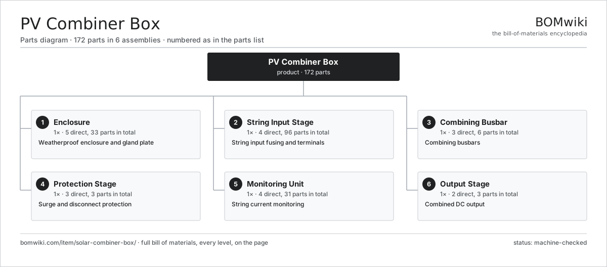
| # | Part | Qty | What it does |
|---|---|---|---|
| 1 | Enclosure 5 parts | 1× | Weatherproof enclosure and gland plate |
| 2 | String Input Stage 4 parts | 1× | String input fusing and terminals |
| 3 | Combining Busbar 3 parts | 1× | Combining busbars |
| 4 | Protection Stage 3 parts | 1× | Surge and disconnect protection |
| 5 | Monitoring Unit 4 parts | 1× | String current monitoring |
| 6 | Output Stage 2 parts | 1× | Combined DC output |
3D model
No 3D model yet. Have a CAD file of this? Add a 3D model — STL renders right on this page; STEP, FreeCAD, and OpenSCAD sources are welcome too (openly licensed, like all 3D models on BOMwiki).
Build & assembly graph
expand / collapse · shared sub-assemblies converge · links to related products · est. labourTap an assembly to expand/collapse · tap a part to open it · use “Open page” for any node · drag to pan, scroll to zoom.
Bill of materials for PV Combiner Box
6 top-level lines · 41 rows shown · 172 parts total · indented to 3 levels| # | Item / sub-assembly | Part no. | Qty/assy | Ext. qty | Parts | Type |
|---|---|---|---|---|---|---|
| 1 | Enclosure 5 parts | solar-combiner-box-enclosure | 1× | 1 | 33 | assembly |
| 1.1 | Box Body | solar-combiner-box-shell | 1× | 1 | · | part |
| 1.2 | Enclosure Door 1 parts | solar-combiner-box-door | 1× | 1 | · | part |
| 1.2.1 | O-Ring Set | oring-set | 1× | 1 | · | part |
| 1.3 | Gland Plate | solar-combiner-box-gland-plate | 1× | 1 | · | part |
| 1.4 | DIN Rail | solar-combiner-box-din-rail | 2× | 2 | · | part |
| 1.5 | Cable Gland | solar-combiner-box-cable-gland | 28× | 28 | · | part |
| 2 | String Input Stage 4 parts | solar-combiner-box-input-stage | 1× | 1 | 96 | assembly |
| 2.1 | Fuse Holder | solar-combiner-box-fuse-holder | 24× | 24 | · | part |
| 2.2 | String Fuse | solar-combiner-box-string-fuse | 24× | 24 | · | part |
| 2.3 | Input Terminal 1 parts | solar-combiner-box-input-terminal | 24× | 24 | · | part |
| 2.3.1 | Connector | connector | 1× | 24 | · | part |
| 2.4 | PV Connector 1 parts | solar-combiner-box-mc4-connector | 24× | 24 | · | part |
| 2.4.1 | Connector | connector | 1× | 24 | · | part |
| 3 | Combining Busbar 3 parts | solar-combiner-box-busbar-stage | 1× | 1 | 6 | assembly |
| 3.1 | Positive Busbar | solar-combiner-box-pos-busbar | 1× | 1 | · | part |
| 3.2 | Negative Busbar | solar-combiner-box-neg-busbar | 1× | 1 | · | part |
| 3.3 | Busbar Standoff 1 parts | solar-combiner-box-busbar-support | 4× | 4 | · | part |
| 3.3.1 | Fastener Set | fastener-set | 1× | 4 | · | part |
| 4 | Protection Stage 3 parts | solar-combiner-box-protection | 1× | 1 | 3 | assembly |
| 4.1 | Surge Protector 1 parts | solar-combiner-box-spd | 1× | 1 | · | part |
| 4.1.1 | Relay | relay | 1× | 1 | · | part |
| 4.2 | DC Disconnect 1 parts | solar-combiner-box-disconnect | 1× | 1 | · | part |
| 4.2.1 | Relay | relay | 1× | 1 | · | part |
| 4.3 | Ground Bar | solar-combiner-box-ground-bar | 1× | 1 | · | part |
| 5 | Monitoring Unit 4 parts | solar-combiner-box-monitoring | 1× | 1 | 31 | assembly |
| 5.1 | Current Sensor | solar-combiner-box-hall-sensor | 24× | 24 | · | part |
| 5.2 | Monitoring Board 3 parts | solar-combiner-box-monitor-board | 1× | 1 | · | part |
| 5.2.1 | Microcontroller | mcu | 1× | 1 | · | part |
| 5.2.2 | Bare PCB | pcb-bare | 1× | 1 | · | part |
| 5.2.3 | SMD Passive (R/C/L) | smd-passives | 1× | 1 | · | part |
| 5.3 | Auxiliary Supply 1 parts | solar-combiner-box-aux-supply | 1× | 1 | · | part |
| 5.3.1 | Power Supply | power-supply | 1× | 1 | · | part |
| 5.4 | RS-485 Module 2 parts | solar-combiner-box-rs485 | 1× | 1 | · | part |
| 5.4.1 | Bare PCB | pcb-bare | 1× | 1 | · | part |
| 5.4.2 | Connector | connector | 2× | 2 | · | part |
| 6 | Output Stage 2 parts | solar-combiner-box-output-stage | 1× | 1 | 3 | assembly |
| 6.1 | Output Terminal 1 parts | solar-combiner-box-output-terminal | 2× | 2 | · | part |
| 6.1.1 | Connector | connector | 1× | 2 | · | part |
| 6.2 | Output Cable 1 parts | solar-combiner-box-output-cable | 1× | 1 | · | part |
| 6.2.1 | Wire Bundle | wire-bundle | 1× | 1 | · | part |
Related products
same domain, ranked by shared parts Concentrated Solar Power Receiver
855 parts · shares 2 with this page
Concentrated Solar Power Receiver
855 parts · shares 2 with this page
 Floating Solar Platform
108 parts · shares 2 with this page
Floating Solar Platform
108 parts · shares 2 with this page
 Francis Hydro Turbine
193 parts · shares 2 with this page
Green Hydrogen Electrolyzer Plant
2,171 parts · shares 2 with this page
Francis Hydro Turbine
193 parts · shares 2 with this page
Green Hydrogen Electrolyzer Plant
2,171 parts · shares 2 with this page
 Grid Battery Storage Container
1,438 parts · shares 2 with this page
Grid Battery Storage Container
1,438 parts · shares 2 with this page
Sourcing: possible vendors
Prices, MOQ, and lead times are algorithmic estimates, not quotes, and not claims about these companies. Company mappings are curated by keyword; est. price band $100–$20M. How estimates work| Vendor | HQ | Specialty | MOQ | Lead time |
|---|---|---|---|---|
|
🇩🇰Vestas
vestas.com ↗
|
Aarhus, DK | Wind turbines | 500 units | 12–24 wks |
| firstsolar.com ↗ | Tempe, US | PV modules | 500 units | 12–24 wks |
|
🇨🇳LONGi
longi.com ↗
|
Xi'an, CN | Solar wafers & modules | 500 units | 12–24 wks |
| enphase.com ↗ | Fremont, US | Microinverters & storage | 500 units | 12–24 wks |
|
🇨🇳Sungrow
sungrowpower.com ↗
|
Hefei, CN | Solar inverters & storage | 500 units | 12–24 wks |
962-word article