Grid Flow Battery System
ProductOverview
A grid flow battery system stores electrical energy as the chemical potential between two liquid electrolytes held in separate tanks. This unit uses vanadium redox chemistry, where the same element, vanadium, exists in four oxidation states across the two electrolytes. Power and energy are decoupled: the Cell Stack Assembly sets the power rating, while the volume of electrolyte in the Positive Electrolyte Tank and Negative Electrolyte Tank sets the energy capacity. To build a longer-duration system you add electrolyte and larger tanks without changing the stacks. A typical container delivers 250 kW to 1 MW and stores 1 MWh to 8 MWh, giving 4 to 12 hours of discharge at rated power.
Flow batteries suit long-duration grid storage where lithium-ion becomes costly: renewable firming, peak shifting over many hours, and microgrid backup. The electrolyte does not degrade with cycling, so the system reaches 15,000 to 20,000 cycles and a 20 to 25 year design life with little capacity fade. The aqueous electrolyte is non-flammable, which lowers fire risk relative to lithium chemistries.
How it works: redox flow chemistry
During discharge the negative electrolyte is oxidized from V2+ to V3+, releasing an electron, while the positive electrolyte is reduced from V5+ (present as the VO2+ ion) to V4+ (as VO2+). The electrons flow through the external circuit and the Power Conversion System to do work, while protons cross the membrane inside the cell to balance charge. Charging reverses both reactions. Each cell produces an open-circuit voltage of about 1.4 to 1.6 V depending on state of charge. Forty cells stacked in series give roughly 48 to 60 V at the stack terminals.
The electrolyte holds 1.6 to 1.8 mol/L of vanadium dissolved in 2 to 4 mol/L sulfuric acid. Concentration is limited by vanadium solubility and by precipitation at temperature extremes, which is why the Thermal Management subsystem holds the electrolyte between 10 and 40 degrees C. Above that range V5+ can precipitate; below it V2+ and V3+ salts can crystallize.
Cell stack
The Cell Stack Assembly is the electrochemical core. Each cell is built from a Ion Exchange Membrane that passes protons while blocking vanadium cross-over, two Carbon Felt Electrode layers of porous carbon felt that host the reaction, and a Bipolar Plate that conducts current to the next cell. A molded flow frame around each cell distributes electrolyte evenly across the felt; uneven flow starves part of the electrode and lowers efficiency. Forty of these cells are clamped between two steel end plates by tie rods, with a copper current collector at each end. The gasket and seal set keeps the two electrolytes apart and prevents external leaks. Membrane cross-over slowly transfers vanadium and water between the half-cells, so a rebalancing cell in the Electrolyte Circulation loop periodically restores the electrolyte balance and recovers lost capacity.
Electrolyte and tanks
The two electrolytes are stored in separate acid-resistant HDPE tanks. The negative tank carries a nitrogen blanket because V2+ oxidizes rapidly in contact with air, which would self-discharge the battery and waste capacity. Both tanks carry a vent filter to release hydrogen, which evolves slowly as a side reaction during charging, and to scrub acid mist. The Electrolyte Circulation subsystem moves electrolyte from each tank through the stacks and back at 100 to 400 L/min per loop using sealless magnetic-drive pumps. Pump speed is modulated to match flow to current: high flow at high power, low flow at idle to save parasitic energy. Flow meters and pressure sensors detect blockage or pump failure. Because pump power is a parasitic load, AC round-trip efficiency of 65 to 75 percent is lower than the 75 to 80 percent measured at the DC terminals.
Power conversion and controls
The Power Conversion System is a bidirectional inverter that converts between the variable stack DC voltage and three-phase AC at 400 V or 480 V, 50 or 60 Hz. IGBT modules switched by gate drivers form the bridge, a DC link capacitor bank stabilizes the bus, and line inductors filter the output. The Battery Management System supervises the whole system: it reads cell and stack voltages, uses a dedicated open-circuit-voltage cell to measure state of charge directly (a method unique to flow batteries, since an idle reference cell sees the true electrolyte potential), commands pump speed, and tells the PCS how much power it can safely source or sink. The DC Switchgear and AC Interconnection provides DC fusing and disconnects, an AC main breaker, surge protection, and a revenue-grade meter at the point of interconnection.
Variants and use: duration scaling
Because power and energy scale independently, the same stack count serves a wide range of durations. A 500 kW system paired with 2 MWh of electrolyte gives 4 hours; the same stacks with 6 MWh give 12 hours, limited only by tank size and electrolyte cost. Larger projects parallel several containers on a shared MV transformer. Common deployments include solar-plus-storage firming, where the battery absorbs midday surplus and discharges into the evening peak, and microgrid backup, where multi-hour duration carries critical loads through outages. The non-flammable electrolyte and flat cycle life make the chemistry well suited to dense or remote sites where lithium fire codes or replacement logistics are a concern.
Grid Flow Battery System parts and their functions
9 top-level parts · 1,006 parts in total · full bill of materials below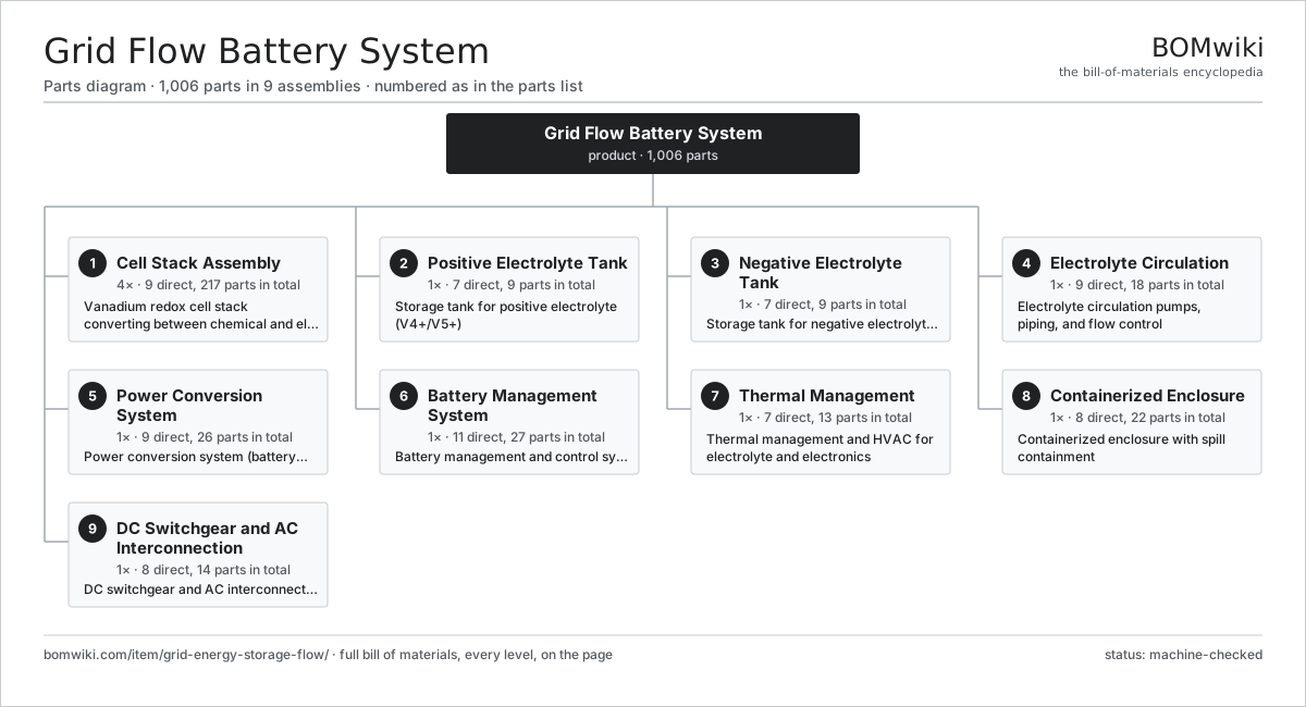
| # | Part | Qty | What it does |
|---|---|---|---|
| 1 | Cell Stack Assembly 9 parts | 4× | Vanadium redox cell stack converting between chemical and electrical energy |
| 2 | Positive Electrolyte Tank 7 parts | 1× | Storage tank for positive electrolyte (V4+/V5+) |
| 3 | Negative Electrolyte Tank 7 parts | 1× | Storage tank for negative electrolyte (V2+/V3+) |
| 4 | Electrolyte Circulation 9 parts | 1× | Electrolyte circulation pumps, piping, and flow control |
| 5 | Power Conversion System 9 parts | 1× | Power conversion system (battery inverter) linking DC stacks to AC grid |
| 6 | Battery Management System 11 parts | 1× | Battery management and control system |
| 7 | Thermal Management 7 parts | 1× | Thermal management and HVAC for electrolyte and electronics |
| 8 | Containerized Enclosure 8 parts | 1× | Containerized enclosure with spill containment |
| 9 | DC Switchgear and AC Interconnection 8 parts | 1× | DC switchgear and AC interconnection |
3D model
No 3D model yet. Have a CAD file of this? Add a 3D model — STL renders right on this page; STEP, FreeCAD, and OpenSCAD sources are welcome too (openly licensed, like all 3D models on BOMwiki).
Build & assembly graph
expand / collapse · shared sub-assemblies converge · links to related products · est. labourTap an assembly to expand/collapse · tap a part to open it · use “Open page” for any node · drag to pan, scroll to zoom.
Bill of materials for Grid Flow Battery System
9 top-level lines · 84 rows shown · 1,006 parts total · indented to 3 levels| # | Item / sub-assembly | Part no. | Qty/assy | Ext. qty | Parts | Type |
|---|---|---|---|---|---|---|
| 1 | Cell Stack Assembly 9 parts | grid-energy-storage-flow-stack | 4× | 4 | 217 | assembly |
| 1.1 | Ion Exchange Membrane | grid-energy-storage-flow-membrane | 40× | 160 | · | part |
| 1.2 | Carbon Felt Electrode | grid-energy-storage-flow-electrode | 80× | 320 | · | part |
| 1.3 | Bipolar Plate | grid-energy-storage-flow-bipolar-plate | 40× | 160 | · | part |
| 1.4 | Flow Frame | grid-energy-storage-flow-flow-frame | 40× | 160 | · | part |
| 1.5 | Stack End Plate | grid-energy-storage-flow-end-plate | 2× | 8 | · | part |
| 1.6 | Current Collector | grid-energy-storage-flow-current-collector | 2× | 8 | · | part |
| 1.7 | Stack Tie Rod | grid-energy-storage-flow-tie-rod | 8× | 32 | · | part |
| 1.8 | O-Ring Set | oring-set | 1× | 4 | · | part |
| 1.9 | Electrolyte Manifold | grid-energy-storage-flow-manifold | 4× | 16 | · | part |
| 2 | Positive Electrolyte Tank 7 parts | grid-energy-storage-flow-positive-tank | 1× | 1 | 9 | assembly |
| 2.1 | Positive Tank Shell | grid-energy-storage-flow-tank-shell-pos | 1× | 1 | · | part |
| 2.2 | Tank Liner | grid-energy-storage-flow-tank-liner | 1× | 1 | · | part |
| 2.3 | Tank Lid | grid-energy-storage-flow-tank-lid | 1× | 1 | · | part |
| 2.4 | Electrolyte Level Sensor | grid-energy-storage-flow-level-sensor | 1× | 1 | · | part |
| 2.5 | Positive Electrolyte | grid-energy-storage-flow-electrolyte-pos | 1× | 1 | · | part |
| 2.6 | Vent Filter | grid-energy-storage-flow-vent-filter | 1× | 1 | · | part |
| 2.7 | Tank Bulkhead Fitting | grid-energy-storage-flow-tank-fitting | 3× | 3 | · | part |
| 3 | Negative Electrolyte Tank 7 parts | grid-energy-storage-flow-negative-tank | 1× | 1 | 9 | assembly |
| 3.1 | Negative Tank Shell | grid-energy-storage-flow-tank-shell-neg | 1× | 1 | · | part |
| 3.2 | Tank Liner | grid-energy-storage-flow-tank-liner | 1× | 1 | · | part |
| 3.3 | Tank Lid | grid-energy-storage-flow-tank-lid | 1× | 1 | · | part |
| 3.4 | Electrolyte Level Sensor | grid-energy-storage-flow-level-sensor | 1× | 1 | · | part |
| 3.5 | Negative Electrolyte | grid-energy-storage-flow-electrolyte-neg | 1× | 1 | · | part |
| 3.6 | Nitrogen Blanket Regulator | grid-energy-storage-flow-nitrogen-purge | 1× | 1 | · | part |
| 3.7 | Tank Bulkhead Fitting | grid-energy-storage-flow-tank-fitting | 3× | 3 | · | part |
| 4 | Electrolyte Circulation 9 parts | grid-energy-storage-flow-circulation | 1× | 1 | 18 | assembly |
| 4.1 | Electrolyte Pump | grid-energy-storage-flow-pump | 2× | 2 | · | part |
| 4.2 | Pump Motor | grid-energy-storage-flow-pump-motor | 2× | 2 | · | part |
| 4.3 | CPVC Piping | grid-energy-storage-flow-pipe-cpvc | 1× | 1 | · | part |
| 4.4 | Electrolyte Flow Meter | grid-energy-storage-flow-flow-meter | 2× | 2 | · | part |
| 4.5 | Isolation Valve | grid-energy-storage-flow-isolation-valve | 4× | 4 | · | part |
| 4.6 | Check Valve | grid-energy-storage-flow-check-valve | 2× | 2 | · | part |
| 4.7 | Pressure Sensor | pressure-sensor | 2× | 2 | · | part |
| 4.8 | Inline Strainer | grid-energy-storage-flow-strainer | 2× | 2 | · | part |
| 4.9 | Rebalancing Cell | grid-energy-storage-flow-rebalance-cell | 1× | 1 | · | part |
| 5 | Power Conversion System 9 parts | grid-energy-storage-flow-pcs | 1× | 1 | 26 | assembly |
| 5.1 | IGBT Power Module | grid-energy-storage-flow-igbt-module | 6× | 6 | · | part |
| 5.2 | DC Link Capacitor | grid-energy-storage-flow-dc-link-cap | 4× | 4 | · | part |
| 5.3 | AC Line Inductor | grid-energy-storage-flow-line-inductor | 3× | 3 | · | part |
| 5.4 | Gate Driver Board | grid-energy-storage-flow-gate-driver | 6× | 6 | · | part |
| 5.5 | Inverter Controller | grid-energy-storage-flow-inverter-controller | 1× | 1 | · | part |
| 5.6 | Liquid Cold Plate | grid-energy-storage-flow-heatsink | 2× | 2 | · | part |
| 5.7 | AC Contactor | grid-energy-storage-flow-ac-contactor | 1× | 1 | · | part |
| 5.8 | DC Precharge Circuit | grid-energy-storage-flow-dc-precharge | 1× | 1 | · | part |
| 5.9 | Bare PCB | pcb-bare | 2× | 2 | · | part |
| 6 | Battery Management System 11 parts | grid-energy-storage-flow-bms | 1× | 1 | 27 | assembly |
| 6.1 | Microcontroller | mcu | 1× | 1 | · | part |
| 6.2 | Bare PCB | pcb-bare | 1× | 1 | · | part |
| 6.3 | State of Charge Cell | grid-energy-storage-flow-soc-sensor | 1× | 1 | · | part |
| 6.4 | Stack Voltage Monitor | grid-energy-storage-flow-voltage-monitor | 4× | 4 | · | part |
| 6.5 | DC Current Shunt | grid-energy-storage-flow-current-shunt | 2× | 2 | · | part |
| 6.6 | Operator Touchscreen | grid-energy-storage-flow-hmi | 1× | 1 | · | part |
| 6.7 | Communications Gateway | grid-energy-storage-flow-comms-gateway | 1× | 1 | · | part |
| 6.8 | Relay | relay | 6× | 6 | · | part |
| 6.9 | Connector | connector | 8× | 8 | · | part |
| 6.10 | Wire Bundle | wire-bundle | 1× | 1 | · | part |
| 6.11 | Power Supply | power-supply | 1× | 1 | · | part |
| 7 | Thermal Management 7 parts | grid-energy-storage-flow-thermal | 1× | 1 | 13 | assembly |
| 7.1 | Plate Heat Exchanger | grid-energy-storage-flow-heat-exchanger | 2× | 2 | · | part |
| 7.2 | Glycol Chiller | grid-energy-storage-flow-chiller | 1× | 1 | · | part |
| 7.3 | Coolant Pump | grid-energy-storage-flow-coolant-pump | 1× | 1 | · | part |
| 7.4 | Container HVAC Unit | grid-energy-storage-flow-hvac-unit | 1× | 1 | · | part |
| 7.5 | Temperature Sensor | grid-energy-storage-flow-temp-sensor | 6× | 6 | · | part |
| 7.6 | Heating Element | heating-element | 1× | 1 | · | part |
| 7.7 | Pressure Sensor | pressure-sensor | 1× | 1 | · | part |
| 8 | Containerized Enclosure 8 parts | grid-energy-storage-flow-enclosure | 1× | 1 | 22 | assembly |
| 8.1 | Container Frame | grid-energy-storage-flow-container-frame | 1× | 1 | · | part |
| 8.2 | Sheet Metal Panel | sheet-panel | 12× | 12 | · | part |
| 8.3 | Spill Containment Tray | grid-energy-storage-flow-spill-tray | 1× | 1 | · | part |
| 8.4 | Exhaust Fan | grid-energy-storage-flow-exhaust-fan | 2× | 2 | · | part |
| 8.5 | Hydrogen Gas Detector | grid-energy-storage-flow-gas-detector | 2× | 2 | · | part |
| 8.6 | Fire Detection Panel | grid-energy-storage-flow-fire-panel | 1× | 1 | · | part |
| 8.7 | Access Door | grid-energy-storage-flow-access-door | 2× | 2 | · | part |
| 8.8 | Fastener Set | fastener-set | 1× | 1 | · | part |
| 9 | DC Switchgear and AC Interconnection 8 parts | grid-energy-storage-flow-switchgear | 1× | 1 | 14 | assembly |
| 9.1 | DC Circuit Breaker | grid-energy-storage-flow-dc-breaker | 2× | 2 | · | part |
| 9.2 | DC Fuse | grid-energy-storage-flow-dc-fuse | 4× | 4 | · | part |
| 9.3 | DC Busbar | grid-energy-storage-flow-dc-busbar | 1× | 1 | · | part |
| 9.4 | AC Circuit Breaker | grid-energy-storage-flow-ac-breaker | 1× | 1 | · | part |
| 9.5 | Revenue Meter | grid-energy-storage-flow-revenue-meter | 1× | 1 | · | part |
| 9.6 | Surge Arrester | grid-energy-storage-flow-surge-arrester | 3× | 3 | · | part |
| 9.7 | Grounding Bar | grid-energy-storage-flow-ground-bar | 1× | 1 | · | part |
| 9.8 | Wire Bundle | wire-bundle | 1× | 1 | · | part |
Related products
same domain, ranked by shared parts Concentrated Solar Power Receiver
855 parts · shares 5 with this page
Green Hydrogen Electrolyzer Plant
2,171 parts · shares 5 with this page
Utility-Scale Solar Inverter
204 parts · shares 5 with this page
Concentrated Solar Power Receiver
855 parts · shares 5 with this page
Green Hydrogen Electrolyzer Plant
2,171 parts · shares 5 with this page
Utility-Scale Solar Inverter
204 parts · shares 5 with this page
 Wind Turbine
28,312 parts · shares 5 with this page
Wind Turbine
28,312 parts · shares 5 with this page
 Wind Turbine Nacelle
287 parts · shares 5 with this page
Wind Turbine Nacelle
287 parts · shares 5 with this page
 PEM Hydrogen Electrolyzer
305 parts · shares 4 with this page
PEM Hydrogen Electrolyzer
305 parts · shares 4 with this page
Sourcing: possible vendors
Prices, MOQ, and lead times are algorithmic estimates, not quotes, and not claims about these companies. Company mappings are curated by keyword; est. price band $100–$20M. How estimates work| Vendor | HQ | Specialty | MOQ | Lead time |
|---|---|---|---|---|
|
🇩🇰Vestas
vestas.com ↗
|
Aarhus, DK | Wind turbines | 500 units | 12–24 wks |
| firstsolar.com ↗ | Tempe, US | PV modules | 500 units | 12–24 wks |
|
🇨🇳LONGi
longi.com ↗
|
Xi'an, CN | Solar wafers & modules | 500 units | 12–24 wks |
| enphase.com ↗ | Fremont, US | Microinverters & storage | 500 units | 12–24 wks |
|
🇨🇳Sungrow
sungrowpower.com ↗
|
Hefei, CN | Solar inverters & storage | 500 units | 12–24 wks |
929-word article