Pelton Hydro Turbine
ProductOverview
A Pelton turbine is an impulse machine that turns the energy of high-head water into shaft power by firing one or more fast jets at a wheel of split buckets. It suits sites where the water falls a long way but the flow is modest, which is the condition in mountain catchments and in plants fed by long high-pressure penstocks. The whole pressure of the head is converted into jet speed in the nozzle before the water ever touches the wheel, so the runner spins in air at atmospheric pressure rather than in a flooded passage. That single fact shapes the entire machine and separates it from reaction turbines such as the Francis Hydro Turbine and the Kaplan Hydro Turbine.
The water arrives through a penstock and is shaped into jets by the Injector Nozzle injectors. Each jet strikes the Runner Wheel, which gives up its torque through the Shaft Line to the generator. Spent water falls into the Turbine Casing and drains to the tailrace. Speed is held by the Speed Governor, with the Jet Deflector standing by for sudden load loss, while the Lubrication Unit unit and the Control Cabinet cabinet keep the bearings fed and the unit supervised.
The runner and buckets
The Runner Wheel is the heart of the machine. A forged Runner Disc carries a ring of double Pelton Bucket cups around its rim, each shaped as two half-ellipsoids meeting at a sharp central Bucket Splitter ridge. When a jet hits the splitter it divides evenly into the two halves, sweeps around the inside of each cup, and leaves at the rim turned through almost 180 degrees. Reversing the water's direction extracts nearly all of its momentum, which is why a Pelton wheel reaches around 90 percent efficiency. The buckets are notched at the lip so that an incoming jet clears the back of the bucket ahead of it and is not cut off early. Runner and buckets are cast or forged in 13-4 stainless steel because the jet is abrasive and prone to cavitation pitting, and the assembly locks to the shaft through the Runner Hub.
Forming and controlling the jet
Each Injector Nozzle turns penstock pressure into a coherent jet and meters how much water flows. A hardened Nozzle Tip ring shapes the final stream, and a conical Needle Spear slides forward and back inside it to vary the jet diameter without breaking up the jet. Moving the spear is the main way the turbine follows load: the Spear Servo drives it with a Servo Piston in an oil Servo Cylinder, while an LVDT Position Sensor feeds spear travel back to the governor. The Nozzle Body turns the flow from the penstock toward the runner and houses the spear gear. Because the jet erodes the tip and spear, both are hardened and made replaceable.
Shaft line and bearings
The Shaft Line carries runner torque to the generator and holds the wheel exactly on the jet line. A forged Main Shaft runs in oil-film Guide Bearing sleeves that keep it radially located, and a tilting-pad Thrust Bearing takes the axial load on vertical units. The shaft joins the generator through a rigid Coupling, and Oil Seal elements keep oil in and spray out. Horizontal units commonly drive a generator with one or two jets, while large vertical units mount four to six nozzles around a single runner to pass more flow at the same speed.
Speed governing and load rejection
A hydro unit must hold the speed that fixes grid frequency, so the Speed Governor continuously trims flow. Its Governor Pump keeps oil pressurised and a gas-charged Accumulator stores energy for fast servo moves, which the Distributing Valve spools route to the spear and deflector. A Speed Pickup reads runner speed and the Governor Controller compares it to setpoint. The hard problem is a sudden loss of load: closing the spear quickly would slam the long penstock and cause a damaging pressure surge. The answer is the Jet Deflector, whose Deflector Plate swings on its Deflector Linkage through the jet in a fraction of a second, driven by the Deflector Servo. The plate steers water away from the buckets at once, unloading the runner, while the spear closes slowly enough to keep the penstock pressure within limits.
Auxiliaries, housing, and supervision
The Lubrication Unit unit supplies the bearings: a Lube Pump circulates oil from the Oil Reservoir through a Oil Cooler and Oil Filter elements so the metal runs cool and clean. The Turbine Casing is a fabricated Casing Shell backed by a steel Pit Liner, with Inspection Door panels for bucket checks and a Tailrace Trough that carries spent water away. The Control Cabinet cabinet runs the start and stop sequence through its Unit PLC, watches a Vibration Monitor, and trips the unit on fault.
Where Pelton turbines fit
Pelton machines own the high-head, low-flow end of hydropower, from small mountain micro-hydro to large alpine plants of several hundred megawatts. Their efficiency curve is unusually flat, so they hold good efficiency down to a small fraction of rated flow simply by closing the spear or shutting off individual jets, which makes them well suited to peaking and to streams whose flow swings through the year. Where the head is medium and the flow large, designers choose a Francis Hydro Turbine instead, and for very low head a Kaplan Hydro Turbine or bulb-turbine. The Pelton's combination of a simple air-running wheel, replaceable jet parts, and fast deflector-based load rejection keeps it the standard answer wherever water falls a long way to reach the powerhouse.
Pelton Hydro Turbine parts and their functions
8 top-level parts · 111 parts in total · full bill of materials below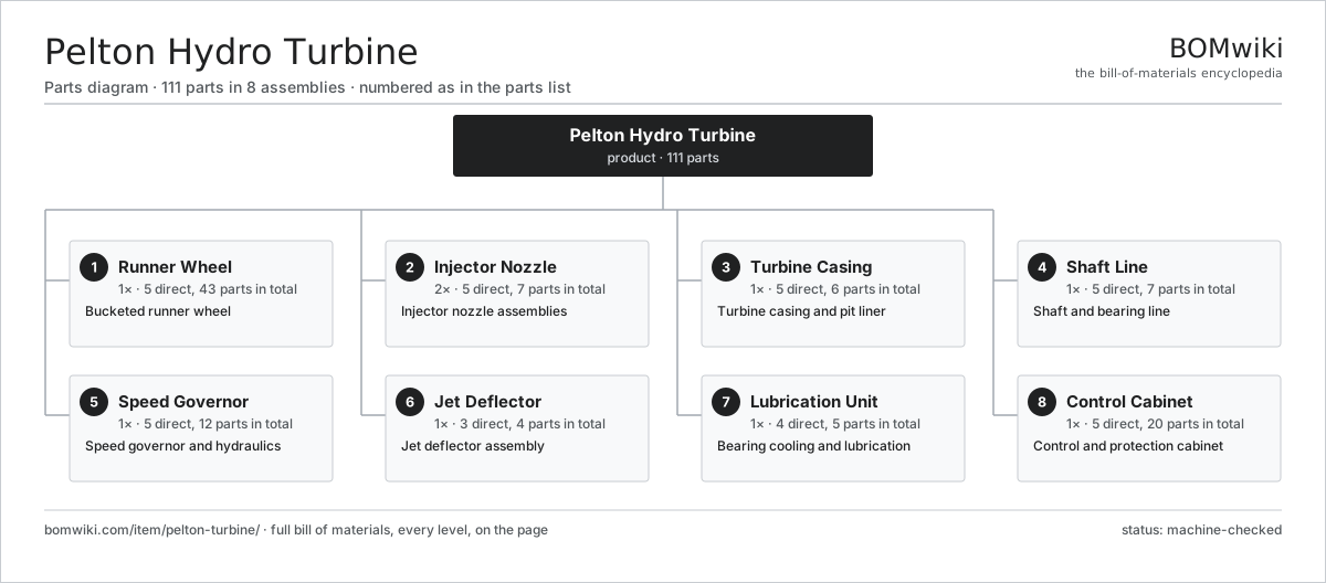
| # | Part | Qty | What it does |
|---|---|---|---|
| 1 | Runner Wheel 5 parts | 1× | Bucketed runner wheel |
| 2 | Injector Nozzle 5 parts | 2× | Injector nozzle assemblies |
| 3 | Turbine Casing 5 parts | 1× | Turbine casing and pit liner |
| 4 | Shaft Line 5 parts | 1× | Shaft and bearing line |
| 5 | Speed Governor 5 parts | 1× | Speed governor and hydraulics |
| 6 | Jet Deflector 3 parts | 1× | Jet deflector assembly |
| 7 | Lubrication Unit 4 parts | 1× | Bearing cooling and lubrication |
| 8 | Control Cabinet 5 parts | 1× | Control and protection cabinet |
3D model
No 3D model yet. Have a CAD file of this? Add a 3D model — STL renders right on this page; STEP, FreeCAD, and OpenSCAD sources are welcome too (openly licensed, like all 3D models on BOMwiki).
Build & assembly graph
expand / collapse · shared sub-assemblies converge · links to related products · est. labourTap an assembly to expand/collapse · tap a part to open it · use “Open page” for any node · drag to pan, scroll to zoom.
Bill of materials for Pelton Hydro Turbine
8 top-level lines · 56 rows shown · 111 parts total · indented to 3 levels| # | Item / sub-assembly | Part no. | Qty/assy | Ext. qty | Parts | Type |
|---|---|---|---|---|---|---|
| 1 | Runner Wheel 5 parts | pelton-turbine-runner | 1× | 1 | 43 | assembly |
| 1.1 | Runner Disc | pelton-turbine-runner-disc | 1× | 1 | · | part |
| 1.2 | Pelton Bucket | pelton-turbine-bucket | 20× | 20 | · | part |
| 1.3 | Bucket Splitter | pelton-turbine-splitter | 20× | 20 | · | part |
| 1.4 | Runner Hub | pelton-turbine-runner-hub | 1× | 1 | · | part |
| 1.5 | Fastener Set | fastener-set | 1× | 1 | · | part |
| 2 | Injector Nozzle 5 parts | pelton-turbine-nozzle-set | 2× | 2 | 7 | assembly |
| 2.1 | Nozzle Tip | pelton-turbine-nozzle-tip | 1× | 2 | · | part |
| 2.2 | Needle Spear | pelton-turbine-spear | 1× | 2 | · | part |
| 2.3 | Spear Servo 3 parts | pelton-turbine-spear-servo | 1× | 2 | 3 | assembly |
| 2.3.1 | Servo Cylinder | pelton-turbine-servo-cylinder | 1× | 2 | · | part |
| 2.3.2 | Servo Piston | pelton-turbine-servo-piston | 1× | 2 | · | part |
| 2.3.3 | Position Sensor | pelton-turbine-position-sensor | 1× | 2 | · | part |
| 2.4 | Nozzle Body | pelton-turbine-nozzle-body | 1× | 2 | · | part |
| 2.5 | O-Ring Set | oring-set | 1× | 2 | · | part |
| 3 | Turbine Casing 5 parts | pelton-turbine-housing | 1× | 1 | 6 | assembly |
| 3.1 | Casing Shell | pelton-turbine-casing-shell | 1× | 1 | · | part |
| 3.2 | Pit Liner | pelton-turbine-pit-liner | 1× | 1 | · | part |
| 3.3 | Inspection Door | pelton-turbine-inspection-door | 2× | 2 | · | part |
| 3.4 | Tailrace Trough | pelton-turbine-tailrace-trough | 1× | 1 | · | part |
| 3.5 | Fastener Set | fastener-set | 1× | 1 | · | part |
| 4 | Shaft Line 5 parts | pelton-turbine-shaft-line | 1× | 1 | 7 | assembly |
| 4.1 | Main Shaft | pelton-turbine-main-shaft | 1× | 1 | · | part |
| 4.2 | Guide Bearing | pelton-turbine-guide-bearing | 2× | 2 | · | part |
| 4.3 | Thrust Bearing | pelton-turbine-thrust-bearing | 1× | 1 | · | part |
| 4.4 | Coupling | pelton-turbine-coupling | 1× | 1 | · | part |
| 4.5 | Oil Seal | oil-seal | 2× | 2 | · | part |
| 5 | Speed Governor 5 parts | pelton-turbine-governor | 1× | 1 | 12 | assembly |
| 5.1 | Governor Pump | pelton-turbine-gov-pump | 1× | 1 | · | part |
| 5.2 | Accumulator | pelton-turbine-gov-accumulator | 1× | 1 | · | part |
| 5.3 | Distributing Valve | pelton-turbine-gov-valve | 2× | 2 | · | part |
| 5.4 | Speed Pickup | pelton-turbine-speed-pickup | 1× | 1 | · | part |
| 5.5 | Governor Controller 4 parts | pelton-turbine-gov-controller | 1× | 1 | 7 | assembly |
| 5.5.1 | Bare PCB | pcb-bare | 1× | 1 | · | part |
| 5.5.2 | Microcontroller | mcu | 1× | 1 | · | part |
| 5.5.3 | SMD Passive (R/C/L) | smd-passives | 1× | 1 | · | part |
| 5.5.4 | Connector | connector | 4× | 4 | · | part |
| 6 | Jet Deflector 3 parts | pelton-turbine-deflector | 1× | 1 | 4 | assembly |
| 6.1 | Deflector Plate | pelton-turbine-deflector-plate | 2× | 2 | · | part |
| 6.2 | Deflector Servo | pelton-turbine-deflector-servo | 1× | 1 | · | part |
| 6.3 | Deflector Linkage | pelton-turbine-deflector-link | 1× | 1 | · | part |
| 7 | Lubrication Unit 4 parts | pelton-turbine-cooling | 1× | 1 | 5 | assembly |
| 7.1 | Lube Pump | pelton-turbine-lube-pump | 1× | 1 | · | part |
| 7.2 | Oil Cooler | pelton-turbine-oil-cooler | 1× | 1 | · | part |
| 7.3 | Oil Filter | pelton-turbine-oil-filter | 2× | 2 | · | part |
| 7.4 | Oil Reservoir | pelton-turbine-oil-tank | 1× | 1 | · | part |
| 8 | Control Cabinet 5 parts | pelton-turbine-controls | 1× | 1 | 20 | assembly |
| 8.1 | Unit PLC 4 parts | pelton-turbine-plc | 1× | 1 | 9 | assembly |
| 8.1.1 | Bare PCB | pcb-bare | 1× | 1 | · | part |
| 8.1.2 | Microcontroller | mcu | 1× | 1 | · | part |
| 8.1.3 | SMD Passive (R/C/L) | smd-passives | 1× | 1 | · | part |
| 8.1.4 | Connector | connector | 6× | 6 | · | part |
| 8.2 | Vibration Monitor | pelton-turbine-vibration-monitor | 1× | 1 | · | part |
| 8.3 | Power Supply | power-supply | 1× | 1 | · | part |
| 8.4 | Relay | relay | 8× | 8 | · | part |
| 8.5 | Wire Bundle | wire-bundle | 1× | 1 | · | part |
Related products
same domain, ranked by shared parts Concentrated Solar Power Receiver
855 parts · shares 3 with this page
Green Hydrogen Electrolyzer Plant
2,171 parts · shares 3 with this page
Utility-Scale Solar Inverter
204 parts · shares 3 with this page
Concentrated Solar Power Receiver
855 parts · shares 3 with this page
Green Hydrogen Electrolyzer Plant
2,171 parts · shares 3 with this page
Utility-Scale Solar Inverter
204 parts · shares 3 with this page
 Wind Turbine
28,312 parts · shares 3 with this page
Wind Turbine
28,312 parts · shares 3 with this page
 Wind Turbine Nacelle
287 parts · shares 3 with this page
Wind Turbine Nacelle
287 parts · shares 3 with this page
Sourcing: possible vendors
Prices, MOQ, and lead times are algorithmic estimates, not quotes, and not claims about these companies. Company mappings are curated by keyword; est. price band $100–$20M. How estimates work| Vendor | HQ | Specialty | MOQ | Lead time |
|---|---|---|---|---|
|
🇩🇰Vestas
vestas.com ↗
|
Aarhus, DK | Wind turbines | 500 units | 12–24 wks |
| firstsolar.com ↗ | Tempe, US | PV modules | 500 units | 12–24 wks |
|
🇨🇳LONGi
longi.com ↗
|
Xi'an, CN | Solar wafers & modules | 500 units | 12–24 wks |
| enphase.com ↗ | Fremont, US | Microinverters & storage | 500 units | 12–24 wks |
|
🇨🇳Sungrow
sungrowpower.com ↗
|
Hefei, CN | Solar inverters & storage | 500 units | 12–24 wks |
1,025-word article