Utility-Scale Solar Inverter
ProductOverview
A utility-scale solar inverter is the power-conversion heart of a solar farm. It takes the high-voltage direct current produced by thousands of photovoltaic modules and converts it into three-phase alternating current that is synchronized with, and exported to, the grid. A central inverter handles 1.5 to 5 MVA in a single unit, and a large plant uses dozens or hundreds of them. Beyond the conversion itself, a modern utility inverter is the device that lets the solar plant behave like a controllable generator, holding voltage, supplying reactive power and riding through grid disturbances under the grid code.
The unit is built from seven subsystems. The DC input stage gathers and protects the array current; the power conversion stage performs the DC-to-AC inversion; the AC output stage cleans and connects the output; the cooling system removes the switching losses; the control unit runs all the algorithms; the enclosure makes it survive outdoors; and the auxiliary power subsystem feeds its own controls.
DC Input Stage
Strings of modules arrive at the DC input stage at up to 1500 V DC. Currents combine on a tin-plated copper DC busbar, and each combined feed passes through a string fuse that protects against reverse current if one string is shaded or faulted. A motorized DC disconnect isolates the whole array so technicians can work safely, and DC surge protectors clamp lightning transients arriving down the field cabling. Before the bridge can connect to the bus, a precharge circuit charges the large DC-link capacitors through a resistor to avoid a damaging inrush.
Power Conversion Stage
The power conversion stage is where direct current becomes alternating current. Six IGBT modules, arranged as three half-bridges, switch the DC bus several thousand times a second under pulse-width modulation to synthesize three sine-shaped currents. A bank of DC-link capacitors stiffens the bus against the ripple this switching creates, and a laminated busbar keeps the loop inductance low so the IGBTs switch cleanly. Each IGBT is commanded by an isolated gate driver with desaturation protection that turns the device off in microseconds during a short circuit. Three output current sensors close the control loop and trip the protection.
AC Output Stage
The raw bridge output is a chopped waveform, so the AC output stage filters it. Three line reactors in series with the output, combined with filter capacitors in shunt, form an LCL filter that removes the switching ripple and leaves a low-distortion sine current within grid harmonic limits. A main AC contactor connects and disconnects the inverter from the grid, an AC breaker provides short-circuit and overload protection, and an AC surge protector guards the terminals.
Cooling System
IGBT switching losses become heat that must be removed continuously. The cooling system clamps each module to an aluminum cold plate through which water-glycol coolant flows. A coolant pump drives the loop out to an external dry cooler, a finned radiator with EC fans that rejects the heat to ambient air. An expansion tank absorbs thermal expansion and holds makeup coolant, while pressure sensors watch flow and pressure so the inverter derates rather than overheats if cooling degrades. Liquid cooling lets a central inverter pack a large power rating into a compact, sealed cabinet that keeps dust away from the electronics.
Control Unit
The control unit turns the hardware into a smart generator. Its control board runs maximum power point tracking (MPPT), continuously adjusting the DC operating voltage to extract the most energy as sun and temperature change, along with the fast current-control loops that shape the IGBT switching. A grid meter measures grid voltage and frequency so the inverter can deliver grid-support functions: reactive power for voltage regulation, low-voltage ride-through during faults, and frequency-watt response. An insulation monitor watches the DC array's resistance to ground and flags insulation faults before they become hazards. A local HMI display serves field staff and a communication gateway links the unit to plant SCADA over Modbus TCP and IEC 61850.
Enclosure and Auxiliary Power
The enclosure is a powder-coated steel cabinet with a sun shield, gasketed service doors and louvred vent filters that keep dust out while allowing airflow. A thermostatic cabinet heater prevents overnight condensation. The whole control system is fed by auxiliary power: an auxiliary supply derives low-voltage control power, a control UPS keeps controls and comms alive through a grid outage for an orderly shutdown, an internal wiring loom ties the compartments together, and a copper grounding bar bonds everything.
Use
Central inverters sit in dedicated power-conversion stations across a solar farm, usually paired with a medium-voltage step-up transformer and switchgear in a containerized skid. They are chosen for the lowest cost per watt at gigawatt scale, where their concentrated power rating and shared infrastructure beat the distributed approach of string inverters. They run for two decades with scheduled filter and coolant maintenance, and increasingly provide the grid services that let high-penetration solar plants stabilize the network rather than merely feed it.
Utility-Scale Solar Inverter parts and their functions
7 top-level parts · 204 parts in total · full bill of materials below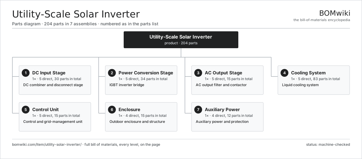
| # | Part | Qty | What it does |
|---|---|---|---|
| 1 | DC Input Stage 5 parts | 1× | DC combiner and disconnect stage |
| 2 | Power Conversion Stage 5 parts | 1× | IGBT inverter bridge |
| 3 | AC Output Stage 5 parts | 1× | AC output filter and contactor |
| 4 | Cooling System 5 parts | 1× | Liquid cooling system |
| 5 | Control Unit 5 parts | 1× | Control and grid-management unit |
| 6 | Enclosure 4 parts | 1× | Outdoor enclosure and structure |
| 7 | Auxiliary Power 4 parts | 1× | Auxiliary power and protection |
3D model
No 3D model yet. Have a CAD file of this? Add a 3D model — STL renders right on this page; STEP, FreeCAD, and OpenSCAD sources are welcome too (openly licensed, like all 3D models on BOMwiki).
Build & assembly graph
expand / collapse · shared sub-assemblies converge · links to related products · est. labourTap an assembly to expand/collapse · tap a part to open it · use “Open page” for any node · drag to pan, scroll to zoom.
Bill of materials for Utility-Scale Solar Inverter
7 top-level lines · 68 rows shown · 204 parts total · indented to 3 levels| # | Item / sub-assembly | Part no. | Qty/assy | Ext. qty | Parts | Type |
|---|---|---|---|---|---|---|
| 1 | DC Input Stage 5 parts | utility-solar-inverter-dc-input | 1× | 1 | 30 | assembly |
| 1.1 | DC Busbar | utility-solar-inverter-dc-busbar | 1× | 1 | · | part |
| 1.2 | String Fuse | utility-solar-inverter-dc-fuse | 24× | 24 | · | part |
| 1.3 | DC Disconnect 1 parts | utility-solar-inverter-dc-disconnect | 1× | 1 | · | part |
| 1.3.1 | Relay | relay | 1× | 1 | · | part |
| 1.4 | DC Surge Protector | utility-solar-inverter-dc-spd | 2× | 2 | · | part |
| 1.5 | Precharge Circuit 2 parts | utility-solar-inverter-precharge | 1× | 1 | · | part |
| 1.5.1 | Relay | relay | 1× | 1 | · | part |
| 1.5.2 | Bare PCB | pcb-bare | 1× | 1 | · | part |
| 2 | Power Conversion Stage 5 parts | utility-solar-inverter-power-stage | 1× | 1 | 34 | assembly |
| 2.1 | IGBT Module | utility-solar-inverter-igbt-module | 6× | 6 | · | part |
| 2.2 | DC-Link Capacitor | utility-solar-inverter-dc-capacitor | 12× | 12 | · | part |
| 2.3 | Gate Driver 2 parts | utility-solar-inverter-gate-driver | 6× | 6 | · | part |
| 2.3.1 | Bare PCB | pcb-bare | 1× | 6 | · | part |
| 2.3.2 | SMD Passive (R/C/L) | smd-passives | 1× | 6 | · | part |
| 2.4 | Laminated Busbar | utility-solar-inverter-busbar-lam | 1× | 1 | · | part |
| 2.5 | Output Current Sensor | utility-solar-inverter-current-sensor | 3× | 3 | · | part |
| 3 | AC Output Stage 5 parts | utility-solar-inverter-output-filter | 1× | 1 | 15 | assembly |
| 3.1 | Line Reactor | utility-solar-inverter-line-reactor | 3× | 3 | · | part |
| 3.2 | Filter Capacitor | utility-solar-inverter-filter-cap | 9× | 9 | · | part |
| 3.3 | AC Contactor 1 parts | utility-solar-inverter-ac-contactor | 1× | 1 | · | part |
| 3.3.1 | Relay | relay | 1× | 1 | · | part |
| 3.4 | AC Breaker 1 parts | utility-solar-inverter-ac-breaker | 1× | 1 | · | part |
| 3.4.1 | Relay | relay | 1× | 1 | · | part |
| 3.5 | AC Surge Protector | utility-solar-inverter-ac-spd | 1× | 1 | · | part |
| 4 | Cooling System 5 parts | utility-solar-inverter-cooling | 1× | 1 | 83 | assembly |
| 4.1 | Cold Plate | utility-solar-inverter-cold-plate | 6× | 6 | · | part |
| 4.2 | Coolant Pump 2 parts | utility-solar-inverter-coolant-pump | 1× | 1 | · | part |
| 4.2.1 | Servo Motor 4 parts + deeper › | servo-motor | 1× | 1 | 24 | assembly |
| 4.2.2 | Oil Seal | oil-seal | 2× | 2 | · | part |
| 4.3 | Dry Cooler 1 parts | utility-solar-inverter-dry-cooler | 1× | 1 | · | part |
| 4.3.1 | Servo Motor 4 parts + deeper › | servo-motor | 2× | 2 | 24 | assembly |
| 4.4 | Expansion Tank | utility-solar-inverter-expansion-tank | 1× | 1 | · | part |
| 4.5 | Pressure Sensor | pressure-sensor | 2× | 2 | · | part |
| 5 | Control Unit 5 parts | utility-solar-inverter-control | 1× | 1 | 15 | assembly |
| 5.1 | Control Board 4 parts | utility-solar-inverter-control-board | 1× | 1 | · | part |
| 5.1.1 | Microcontroller | mcu | 2× | 2 | · | part |
| 5.1.2 | Bare PCB | pcb-bare | 1× | 1 | · | part |
| 5.1.3 | SMD Passive (R/C/L) | smd-passives | 1× | 1 | · | part |
| 5.1.4 | Connector | connector | 4× | 4 | · | part |
| 5.2 | Grid Meter 1 parts | utility-solar-inverter-grid-meter | 1× | 1 | · | part |
| 5.2.1 | Bare PCB | pcb-bare | 1× | 1 | · | part |
| 5.3 | HMI Display 2 parts | utility-solar-inverter-hmi | 1× | 1 | · | part |
| 5.3.1 | LCD Panel | lcd-panel | 1× | 1 | · | part |
| 5.3.2 | Microcontroller | mcu | 1× | 1 | · | part |
| 5.4 | Communication Gateway 2 parts | utility-solar-inverter-comms | 1× | 1 | · | part |
| 5.4.1 | Bare PCB | pcb-bare | 1× | 1 | · | part |
| 5.4.2 | Connector | connector | 2× | 2 | · | part |
| 5.5 | Insulation Monitor 1 parts | utility-solar-inverter-isolation-monitor | 1× | 1 | · | part |
| 5.5.1 | Bare PCB | pcb-bare | 1× | 1 | · | part |
| 6 | Enclosure 4 parts | utility-solar-inverter-enclosure | 1× | 1 | 15 | assembly |
| 6.1 | Cabinet Body 1 parts | utility-solar-inverter-cabinet | 1× | 1 | · | part |
| 6.1.1 | Sheet Metal Panel | sheet-panel | 6× | 6 | · | part |
| 6.2 | Service Door 2 parts | utility-solar-inverter-door-set | 2× | 2 | · | part |
| 6.2.1 | O-Ring Set | oring-set | 1× | 2 | · | part |
| 6.2.2 | Fastener Set | fastener-set | 1× | 2 | · | part |
| 6.3 | Vent Filter | utility-solar-inverter-vent-filter | 4× | 4 | · | part |
| 6.4 | Cabinet Heater 1 parts | utility-solar-inverter-heater | 1× | 1 | · | part |
| 6.4.1 | Heating Element | heating-element | 1× | 1 | · | part |
| 7 | Auxiliary Power 4 parts | utility-solar-inverter-aux-power | 1× | 1 | 12 | assembly |
| 7.1 | Auxiliary Supply 1 parts | utility-solar-inverter-aux-supply | 1× | 1 | · | part |
| 7.1.1 | Power Supply | power-supply | 1× | 1 | · | part |
| 7.2 | Control UPS 1 parts | utility-solar-inverter-ups | 1× | 1 | · | part |
| 7.2.1 | Power Supply | power-supply | 1× | 1 | · | part |
| 7.3 | Wiring Loom 2 parts | utility-solar-inverter-wiring | 1× | 1 | · | part |
| 7.3.1 | Wire Bundle | wire-bundle | 1× | 1 | · | part |
| 7.3.2 | Connector | connector | 8× | 8 | · | part |
| 7.4 | Grounding Bar | utility-solar-inverter-ground-bar | 1× | 1 | · | part |
Related products
same domain, ranked by shared parts Wind Turbine
28,312 parts · shares 19 with this page
Wind Turbine
28,312 parts · shares 19 with this page
 Wind Turbine Nacelle
287 parts · shares 19 with this page
Wind Turbine Nacelle
287 parts · shares 19 with this page
 Concentrated Solar Power Receiver
855 parts · shares 18 with this page
Concentrated Solar Power Receiver
855 parts · shares 18 with this page
 Micro Hydro Turbine
159 parts · shares 17 with this page
Micro Hydro Turbine
159 parts · shares 17 with this page
 Floating Offshore Wind Turbine
608 parts · shares 16 with this page
Floating Offshore Wind Turbine
608 parts · shares 16 with this page
Sourcing: possible vendors
Prices, MOQ, and lead times are algorithmic estimates, not quotes, and not claims about these companies. Company mappings are curated by keyword; est. price band $100–$20M. How estimates work| Vendor | HQ | Specialty | MOQ | Lead time |
|---|---|---|---|---|
|
🇩🇰Vestas
vestas.com ↗
|
Aarhus, DK | Wind turbines | 500 units | 12–24 wks |
| firstsolar.com ↗ | Tempe, US | PV modules | 500 units | 12–24 wks |
|
🇨🇳LONGi
longi.com ↗
|
Xi'an, CN | Solar wafers & modules | 500 units | 12–24 wks |
| enphase.com ↗ | Fremont, US | Microinverters & storage | 500 units | 12–24 wks |
|
🇨🇳Sungrow
sungrowpower.com ↗
|
Hefei, CN | Solar inverters & storage | 500 units | 12–24 wks |
1,068-word article