Offshore Wind Monopile Foundation
ProductOverview
A monopile is the simplest and most common foundation for an offshore wind turbine: a single large steel tube driven into the seabed. In shallow to moderate water, up to around 40 metres deep, a tube 6 to 10 metres across and 60 to 90 metres long, weighing well over a thousand tonnes, is hammered into the seafloor until enough of it is buried to hold the turbine upright against wind and waves. On top sits a transition piece, a separately fabricated section that connects the rough driven pile to the precise tower and carries all the access steel. The whole assembly has to survive 25 to 30 years in seawater while a turbine pushes and rocks it millions of times.
The foundation breaks into the structural tube and the systems that finish and protect it. The Monopile Tube is the driven pile, the Transition Piece is the tower interface, and the Connection System joins the two. Around them sit the Secondary Steel for access, the Corrosion Protection that fights seawater, the Cable System that brings power ashore, the Scour Protection that stabilizes the seabed, and the Monitoring System that watches the structure over its life.
Monopile tube
The Monopile Tube is the load-bearing element, built much like a giant pressure vessel. Heavy Heavy Steel Plate, up to 100 mm thick and rolled from S355 structural steel, is cut and bent into individual Rolled Can rings, each closed by a Longitudinal Weld seam. The cans are then stacked and joined by Circumferential Weld girth welds into one long cylinder. A single pile can need 30 cans and as many full-penetration welds, every one ultrasonically inspected, because a hidden flaw becomes a fatigue crack. The bottom ends in a Pile Toe that first cuts into the seabed, while a thickened Driving Shoe at the top absorbs the pile-driving hammer blows.
Transition piece
Driving a pile leaves it slightly tilted and with a rough, out-of-tolerance top, so the turbine is not bolted straight onto it. Instead the Transition Piece slips over the pile head above the waterline. Its TP Shell cylinder is held round by Stiffener Ring rings and carries Internal Platform decks for cable work inside. The piece is set perfectly vertical regardless of the pile's lean, then locked in place, presenting a machined Tower Flange with a Fastener Set bolt circle that the tower bolts to. Rows of Shear Key ribs in the joint surface help lock it to the pile.
Connecting pile and transition piece
The Connection System carries the entire overturning moment of the turbine from the transition piece into the pile. The traditional method is a grouted joint: the annular gap between the two tubes is closed at the bottom with an Grout Seal, and Annulus Grout, a high-strength cementitious mix, is pumped in through an Grout Port until it fills the annulus and sets into a load-bearing ring. Many newer foundations use an Bolted Connection Flange joint with a Fastener Set instead, because early grouted connections on some farms slipped and had to be repaired, and a bolted joint is easier to inspect and re-tension.
Protecting the steel
Seawater is relentless, so the Corrosion Protection system works on several fronts. Above and through the splash zone the steel wears a multi-layer Coating System of epoxy and polyurethane. Below the water the structure is protected cathodically, either by a ring of Sacrificial Anode aluminum blocks that corrode in place of the steel, or by ICCP Anode impressed-current anodes driven by an ICCP Controller that forces a protective current onto the surface. On top of all that, the designer adds a plain Corrosion Allowance of extra wall thickness that is simply allowed to be eaten away slowly over the life of the foundation.
Cables, seabed, and monitoring
Power leaves the turbine through the Cable System. The subsea export cable rises from the seabed inside a steel J-Tube, passes a Bend Restrictor that keeps it from kinking at the entry, is fixed by a Cable Hang-Off clamp inside the transition piece, and is sealed by an Cable Seal gland. Fast tidal currents would otherwise scoop sand from around the pile, so Scour Protection is placed on the seabed: a fine Filter Rock Layer first, then a coarse Armour Rock Layer layer, sometimes seeded with Frond Mat mats that trap sediment. Finally the Monitoring System watches the foundation for decades, with Strain Gauge gauges reading wave load, Tilt Sensor inclinometers checking for lean, Corrosion Probe electrodes confirming the cathodic protection, and an Scour Sonar tracking seabed erosion, all logged by an Data Logger over a Wire Bundle and reported ashore. The Secondary Steel, including the Boat Landing, Access Ladder climbs, an External Platform, Handrail Set guarding, and a small Davit Crane, lets crews reach and maintain all of it.
Offshore Wind Monopile Foundation parts and their functions
8 top-level parts · 382 parts in total · full bill of materials below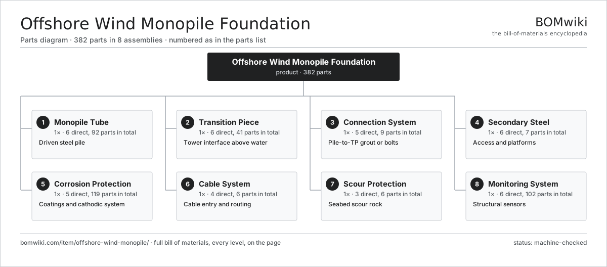
| # | Part | Qty | What it does |
|---|---|---|---|
| 1 | Monopile Tube 6 parts | 1× | Driven steel pile |
| 2 | Transition Piece 6 parts | 1× | Tower interface above water |
| 3 | Connection System 5 parts | 1× | Pile-to-TP grout or bolts |
| 4 | Secondary Steel 6 parts | 1× | Access and platforms |
| 5 | Corrosion Protection 5 parts | 1× | Coatings and cathodic system |
| 6 | Cable System 4 parts | 1× | Cable entry and routing |
| 7 | Scour Protection 3 parts | 1× | Seabed scour rock |
| 8 | Monitoring System 6 parts | 1× | Structural sensors |
3D model
No 3D model yet. Have a CAD file of this? Add a 3D model — STL renders right on this page; STEP, FreeCAD, and OpenSCAD sources are welcome too (openly licensed, like all 3D models on BOMwiki).
Build & assembly graph
expand / collapse · shared sub-assemblies converge · links to related products · est. labourTap an assembly to expand/collapse · tap a part to open it · use “Open page” for any node · drag to pan, scroll to zoom.
Bill of materials for Offshore Wind Monopile Foundation
8 top-level lines · 57 rows shown · 382 parts total · indented to 3 levels| # | Item / sub-assembly | Part no. | Qty/assy | Ext. qty | Parts | Type |
|---|---|---|---|---|---|---|
| 1 | Monopile Tube 6 parts | owm-monopile-tube | 1× | 1 | 92 | assembly |
| 1.1 | Rolled Can | owm-rolled-can | 30× | 30 | · | part |
| 1.2 | Circumferential Weld | owm-circ-weld | 29× | 29 | · | part |
| 1.3 | Longitudinal Weld | owm-long-weld | 30× | 30 | · | part |
| 1.4 | Pile Toe | owm-pile-toe | 1× | 1 | · | part |
| 1.5 | Driving Shoe | owm-driving-shoe | 1× | 1 | · | part |
| 1.6 | Heavy Steel Plate | owm-steel-plate | 1× | 1 | · | part |
| 2 | Transition Piece 6 parts | owm-transition-piece | 1× | 1 | 41 | assembly |
| 2.1 | TP Shell | owm-tp-shell | 1× | 1 | · | part |
| 2.2 | Tower Flange | owm-tower-flange | 1× | 1 | · | part |
| 2.3 | Internal Platform | owm-internal-platform | 2× | 2 | · | part |
| 2.4 | Shear Key | owm-shear-key | 24× | 24 | · | part |
| 2.5 | Stiffener Ring | owm-tp-stiffener | 12× | 12 | · | part |
| 2.6 | Fastener Set | fastener-set | 1× | 1 | · | part |
| 3 | Connection System 5 parts | owm-connection-system | 1× | 1 | 9 | assembly |
| 3.1 | Annulus Grout | owm-grout | 1× | 1 | · | part |
| 3.2 | Grout Seal | owm-grout-seal | 2× | 2 | · | part |
| 3.3 | Grout Port | owm-grout-port | 4× | 4 | · | part |
| 3.4 | Bolted Connection Flange | owm-bolted-flange | 1× | 1 | · | part |
| 3.5 | Fastener Set | fastener-set | 1× | 1 | · | part |
| 4 | Secondary Steel 6 parts | owm-secondary-steel | 1× | 1 | 7 | assembly |
| 4.1 | Boat Landing | owm-boat-landing | 1× | 1 | · | part |
| 4.2 | Access Ladder | owm-access-ladder | 2× | 2 | · | part |
| 4.3 | External Platform | owm-external-platform | 1× | 1 | · | part |
| 4.4 | Handrail Set | owm-handrail | 1× | 1 | · | part |
| 4.5 | Davit Crane | owm-davit-crane | 1× | 1 | · | part |
| 4.6 | Fastener Set | fastener-set | 1× | 1 | · | part |
| 5 | Corrosion Protection 5 parts | owm-corrosion-protection | 1× | 1 | 119 | assembly |
| 5.1 | Coating System | owm-coating-system | 1× | 1 | · | part |
| 5.2 | Sacrificial Anode | owm-sacrificial-anode | 40× | 40 | · | part |
| 5.3 | ICCP Anode | owm-iccp-anode | 4× | 4 | · | part |
| 5.4 | ICCP Controller 4 parts | owm-iccp-controller | 1× | 1 | 73 | assembly |
| 5.4.1 | Bare PCB | pcb-bare | 1× | 1 | · | part |
| 5.4.2 | Microcontroller | mcu | 1× | 1 | · | part |
| 5.4.3 | Power Supply | power-supply | 1× | 1 | · | part |
| 5.4.4 | SMD Passive (R/C/L) | smd-passives | 70× | 70 | · | part |
| 5.5 | Corrosion Allowance | owm-corrosion-allowance | 1× | 1 | · | part |
| 6 | Cable System 4 parts | owm-cable-system | 1× | 1 | 6 | assembly |
| 6.1 | J-Tube | owm-j-tube | 2× | 2 | · | part |
| 6.2 | Cable Hang-Off | owm-cable-hangoff | 1× | 1 | · | part |
| 6.3 | Bend Restrictor | owm-bend-restrictor | 1× | 1 | · | part |
| 6.4 | Cable Seal | owm-cable-seal | 2× | 2 | · | part |
| 7 | Scour Protection 3 parts | owm-scour-protection | 1× | 1 | 6 | assembly |
| 7.1 | Filter Rock Layer | owm-filter-layer | 1× | 1 | · | part |
| 7.2 | Armour Rock Layer | owm-armour-rock | 1× | 1 | · | part |
| 7.3 | Frond Mat | owm-frond-mat | 4× | 4 | · | part |
| 8 | Monitoring System 6 parts | owm-monitoring-system | 1× | 1 | 102 | assembly |
| 8.1 | Strain Gauge | owm-strain-gauge | 8× | 8 | · | part |
| 8.2 | Tilt Sensor | owm-tilt-sensor | 2× | 2 | · | part |
| 8.3 | Corrosion Probe | owm-corrosion-probe | 4× | 4 | · | part |
| 8.4 | Scour Sonar | owm-scour-sonar | 1× | 1 | · | part |
| 8.5 | Data Logger 4 parts | owm-data-logger | 1× | 1 | 86 | assembly |
| 8.5.1 | Bare PCB | pcb-bare | 1× | 1 | · | part |
| 8.5.2 | Microcontroller | mcu | 1× | 1 | · | part |
| 8.5.3 | SMD Passive (R/C/L) | smd-passives | 80× | 80 | · | part |
| 8.5.4 | Connector | connector | 4× | 4 | · | part |
| 8.6 | Wire Bundle | wire-bundle | 1× | 1 | · | part |
Related products
same domain, ranked by shared parts Offshore Wind Jacket Foundation
489 parts · shares 15 with this page
Archimedes Screw Turbine
56 parts · shares 1 with this page
Offshore Wind Jacket Foundation
489 parts · shares 15 with this page
Archimedes Screw Turbine
56 parts · shares 1 with this page
 Battery Energy Storage System
17,429 parts · shares 1 with this page
Biogas Upgrading Unit
110 parts · shares 1 with this page
Battery Energy Storage System
17,429 parts · shares 1 with this page
Biogas Upgrading Unit
110 parts · shares 1 with this page
 Biomass Pellet Plant
404 parts · shares 1 with this page
Biomass Pellet Plant
404 parts · shares 1 with this page
 Concentrated Solar Power Receiver
855 parts · shares 1 with this page
Concentrated Solar Power Receiver
855 parts · shares 1 with this page
Sourcing: possible vendors
Prices, MOQ, and lead times are algorithmic estimates, not quotes, and not claims about these companies. Company mappings are curated by keyword; est. price band $100–$20M. How estimates work| Vendor | HQ | Specialty | MOQ | Lead time |
|---|---|---|---|---|
|
🇩🇰Vestas
vestas.com ↗
|
Aarhus, DK | Wind turbines | 500 units | 12–24 wks |
| firstsolar.com ↗ | Tempe, US | PV modules | 500 units | 12–24 wks |
|
🇨🇳LONGi
longi.com ↗
|
Xi'an, CN | Solar wafers & modules | 500 units | 12–24 wks |
| enphase.com ↗ | Fremont, US | Microinverters & storage | 500 units | 12–24 wks |
|
🇨🇳Sungrow
sungrowpower.com ↗
|
Hefei, CN | Solar inverters & storage | 500 units | 12–24 wks |
859-word article