Wind Turbine Pitch System
ProductOverview
The pitch system controls how hard the wind drives a turbine by twisting each blade about its long axis to change its angle of attack. In light wind the blades sit nearly flat to the airflow to catch as much energy as possible. As wind rises past the rated point, the system feathers them slightly to spill the excess and hold power and rotor speed at their limits. In an emergency it twists the blades all the way to feather, edge-on to the wind, which is the primary aerodynamic brake that brings a runaway rotor safely to a near stop. Because that braking function is a life-safety requirement, the pitch system is one of the most safety-critical assemblies on the whole turbine.
The system lives inside the rotating hub and works on each blade independently. A Wind Turbine Pitch Drive turns each blade on its Pitch Bearing, every drive backed by its own Backup Power so it can feather even with no grid. A Wind Turbine Pitch Control System coordinates the three blades, a Slip Ring carries power and data into the spinning hub, and the Hub Enclosure houses everything against weather and rotation.
Pitch drive
Each blade gets its own Wind Turbine Pitch Drive. It begins with a Pitch Motor, commonly a DC or permanent-magnet motor chosen because it can run from a battery during a grid loss. That motor feeds a Wind Turbine Pitch Gearbox, a planetary reducer built from Planet Set stages and a Sun Gear, which converts the motor's speed into the slow, very high torque needed to rotate a blade that can weigh many tonnes. The output Pitch Pinion meshes the toothed ring on the blade bearing. A Pitch Brake holds the angle when the drive is idle so the aerodynamic load cannot back-drive the blade, and a redundant Pitch Encoder reports the exact angle, with redundancy mandated because a wrong pitch reading could cause an unsafe move.
Pitch bearing
The blade does not rotate against the hub directly; it turns on the Pitch Bearing. This is a Pitch Bearing Ring slewing bearing at the blade root, running on Bearing Roller elements, that carries the entire blade load, its weight, the centrifugal pull, and the aerodynamic bending, while still letting it rotate freely about its axis. As with the yaw ring, the bearing also carries Pitch Ring Gear teeth that the pitch pinion drives, so one component both supports the blade and serves as the gear. Pitch Bearing Seal seals keep the raceway clean and greased, and a heavy Fastener Set bolts the ring between the blade root and the hub.
Backup power and fail-safe feather
The defining feature of an electric pitch system is the Backup Power, because the blades must be able to feather to a stop even if the grid fails at the worst moment, in a storm. Each blade therefore carries stored energy sized to drive a full feather move on its own. Most systems use a Backup Battery, a pack of Battery Cell cells with its own Battery Monitor in a Battery Case, watched closely because a dead backup is itself a safety failure. Some designs instead use a Supercapacitor Bank of Supercapacitor Cell capacitors with a Balancing Board, which deliver the high feather current and last longer. A Backup Charger keeps the store topped up through a Charger Switch output stage, and a Power Converter conditions the supply for the motor. When grid power drops, the system automatically switches to this stored energy and feathers the blades.
Control and safety chain
The three drives are coordinated by the Wind Turbine Pitch Control System. A Pitch Controller takes the pitch demand from the turbine controller and commands each blade through its own Axis Drive, which controls the torque and speed of the move through power switches run by a Gate Driver. Each blade also feeds a Blade Load Sensor back, so the controller can pitch the blades individually by small amounts as they sweep through the uneven wind near the ground, a technique that markedly cuts blade and tower fatigue. Overseeing all of it is a hard-wired Safety Relay in the safety chain: if any critical fault opens that chain, every blade is commanded to feather immediately, bypassing the software, with Relay contactors switching the drives over a hub Wire Bundle.
Slip ring and hub housing
Because the pitch system rotates with the hub while its commands come from the stationary nacelle, power and data must cross a rotating boundary, which is the Slip Ring at the hub center. A stack of Conductive Ring conductive rings with sliding Carbon Brush carbon brushes carries the power and slow signals, while a Fiber Rotary Joint optical joint passes the high-speed control data without electrical noise, all held in a Slip Ring Housing. The whole pitch system is mounted in the Hub Enclosure, where a Pitch Cabinet for each blade holds its drive and backup behind a Hub Access Cover. Inside the sealed hub, a Heater Unit keeps the electronics above the dew point and a Cooling Fan fan removes drive heat, since the hub is closed against weather but the drives still need to shed the energy they burn during every pitch move.
Wind Turbine Pitch System parts and their functions
6 top-level parts · 1,566 parts in total · full bill of materials below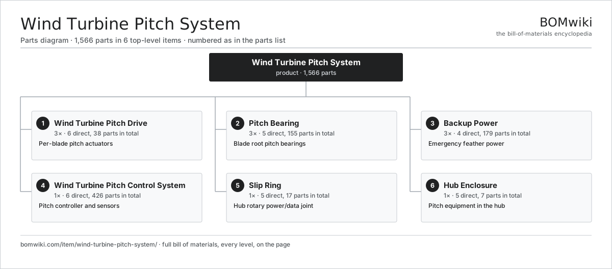
| # | Part | Qty | What it does |
|---|---|---|---|
| 1 | Wind Turbine Pitch Drive 6 parts | 3× | Per-blade pitch actuators |
| 2 | Pitch Bearing 5 parts | 3× | Blade root pitch bearings |
| 3 | Backup Power 4 parts | 3× | Emergency feather power |
| 4 | Wind Turbine Pitch Control System 6 parts | 1× | Pitch controller and sensors |
| 5 | Slip Ring 5 parts | 1× | Hub rotary power/data joint |
| 6 | Hub Enclosure 5 parts | 1× | Pitch equipment in the hub |
3D model
No 3D model yet. Have a CAD file of this? Add a 3D model. STL renders right on this page; STEP, FreeCAD, and OpenSCAD sources are welcome too (openly licensed, like all 3D models on BOMwiki).
Build & assembly graph
expand / collapse · shared sub-assemblies converge · links to related products · est. labourTap an assembly to expand/collapse · tap a part to open it · use “Open page” for any node · drag to pan, scroll to zoom.
Bill of materials for Wind Turbine Pitch System
6 top-level lines · 63 rows shown · 1,566 parts total · indented to 3 levels| # | Item / sub-assembly | Part no. | Qty/assy | Ext. qty | Parts | Type |
|---|---|---|---|---|---|---|
| 1 | Wind Turbine Pitch Drive 6 parts | wps-pitch-drive | 3× | 3 | 38 | assembly |
| 1.1 | Pitch Motor 4 parts | wps-pitch-motor | 1× | 3 | 25 | assembly |
| 1.1.1 | Stator Assembly 3 parts + deeper › | stator-assembly | 1× | 3 | 3 | assembly |
| 1.1.2 | Rotor Assembly 4 parts + deeper › | rotor-assembly | 1× | 3 | 19 | assembly |
| 1.1.3 | Motor Housing | motor-housing | 1× | 3 | · | part |
| 1.1.4 | Ball Bearing | ball-bearing | 2× | 6 | · | part |
| 1.2 | Wind Turbine Pitch Gearbox 4 parts | wps-pitch-gearbox | 1× | 3 | 8 | assembly |
| 1.2.1 | Planet Set | wps-planet-set | 2× | 6 | · | part |
| 1.2.2 | Sun Gear | wps-sun-gear | 1× | 3 | · | part |
| 1.2.3 | Gearbox Housing | gearbox-housing | 1× | 3 | · | part |
| 1.2.4 | Ball Bearing | ball-bearing | 4× | 12 | · | part |
| 1.3 | Pitch Pinion | wps-pinion | 1× | 3 | · | part |
| 1.4 | Pitch Brake | wps-pitch-brake | 1× | 3 | · | part |
| 1.5 | Pitch Encoder | wps-pitch-encoder | 1× | 3 | · | part |
| 1.6 | Oil Seal | oil-seal | 2× | 6 | · | part |
| 2 | Pitch Bearing 5 parts | wps-pitch-bearing | 3× | 3 | 155 | assembly |
| 2.1 | Pitch Bearing Ring | wps-bearing-ring | 1× | 3 | · | part |
| 2.2 | Pitch Ring Gear | wps-ring-gear | 1× | 3 | · | part |
| 2.3 | Bearing Roller | wyd-bearing-roller | 150× | 450 | · | part |
| 2.4 | Pitch Bearing Seal | wps-bearing-seal | 2× | 6 | · | part |
| 2.5 | Fastener Set | fastener-set | 1× | 3 | · | part |
| 3 | Backup Power 4 parts | wps-backup-power | 3× | 3 | 179 | assembly |
| 3.1 | Backup Battery 3 parts | wps-backup-battery | 1× | 3 | 65 | assembly |
| 3.1.1 | Battery Cell | wps-battery-cell | 12× | 36 | · | part |
| 3.1.2 | Battery Monitor 3 parts + deeper › | wps-battery-monitor | 1× | 3 | 52 | assembly |
| 3.1.3 | Battery Case | wps-battery-case | 1× | 3 | · | part |
| 3.2 | Supercapacitor Bank 2 parts | wps-supercap-bank | 1× | 3 | 47 | assembly |
| 3.2.1 | Supercapacitor Cell | wps-supercap-cell | 6× | 18 | · | part |
| 3.2.2 | Balancing Board 2 parts + deeper › | wps-balancing-board | 1× | 3 | 41 | assembly |
| 3.3 | Backup Charger 4 parts | wps-charger | 1× | 3 | 66 | assembly |
| 3.3.1 | Bare PCB | pcb-bare | 1× | 3 | · | part |
| 3.3.2 | Microcontroller | mcu | 1× | 3 | · | part |
| 3.3.3 | Charger Switch | wps-charger-switch | 4× | 12 | · | part |
| 3.3.4 | SMD Passive (R/C/L) | smd-passives | 60× | 180 | · | part |
| 3.4 | Power Converter | wps-power-converter | 1× | 3 | · | part |
| 4 | Wind Turbine Pitch Control System 6 parts | wps-control-system | 1× | 1 | 426 | assembly |
| 4.1 | Pitch Controller 4 parts | wps-pitch-controller | 1× | 1 | 151 | assembly |
| 4.1.1 | Bare PCB | pcb-bare | 1× | 1 | · | part |
| 4.1.2 | Microcontroller | mcu | 2× | 2 | · | part |
| 4.1.3 | SMD Passive (R/C/L) | smd-passives | 140× | 140 | · | part |
| 4.1.4 | Connector | connector | 8× | 8 | · | part |
| 4.2 | Axis Drive 4 parts | wps-axis-drive | 3× | 3 | 88 | assembly |
| 4.2.1 | Bare PCB | pcb-bare | 1× | 3 | · | part |
| 4.2.2 | Power MOSFET | mosfet | 6× | 18 | · | part |
| 4.2.3 | Gate Driver | wps-gate-driver | 1× | 3 | · | part |
| 4.2.4 | SMD Passive (R/C/L) | smd-passives | 80× | 240 | · | part |
| 4.3 | Blade Load Sensor | wps-load-sensor | 3× | 3 | · | part |
| 4.4 | Safety Relay | wps-safety-relay | 1× | 1 | · | part |
| 4.5 | Relay | relay | 6× | 6 | · | part |
| 4.6 | Wire Bundle | wire-bundle | 1× | 1 | · | part |
| 5 | Slip Ring 5 parts | wps-slip-ring | 1× | 1 | 17 | assembly |
| 5.1 | Conductive Ring | wps-slipring-ring | 1× | 1 | · | part |
| 5.2 | Carbon Brush | wps-slipring-brush | 12× | 12 | · | part |
| 5.3 | Fiber Rotary Joint | wps-fiber-rotary | 1× | 1 | · | part |
| 5.4 | Slip Ring Housing | wps-slipring-housing | 1× | 1 | · | part |
| 5.5 | Ball Bearing | ball-bearing | 2× | 2 | · | part |
| 6 | Hub Enclosure 5 parts | wps-hub-enclosure | 1× | 1 | 7 | assembly |
| 6.1 | Pitch Cabinet | wps-pitch-cabinet | 3× | 3 | · | part |
| 6.2 | Hub Access Cover | wps-cabinet-cover | 1× | 1 | · | part |
| 6.3 | Heater Unit 1 parts | wps-heater-unit | 1× | 1 | 1 | assembly |
| 6.3.1 | Heating Element | heating-element | 1× | 1 | · | part |
| 6.4 | Cooling Fan | wps-cabinet-cooling | 1× | 1 | · | part |
| 6.5 | Fastener Set | fastener-set | 1× | 1 | · | part |
Something wrong in this list? Report a problem with this BOM.
Used in 1 assembly
Related products
same domain, ranked by shared parts Wind Turbine
28,312 parts · shares 54 with this page
Wind Turbine Yaw Drive
1,216 parts · shares 14 with this page
 Wind Turbine Nacelle
287 parts · shares 13 with this page
 Vertical-Axis Wind Turbine
99 parts · shares 12 with this page
 Biomass Pellet Plant
404 parts · shares 12 with this page
 Floating Offshore Wind Turbine
608 parts · shares 12 with this page
Sourcing: possible vendors
Browse the supplier directory → Prices, MOQ, and lead times are algorithmic estimates, not quotes, and not claims about these companies. Company mappings are curated by keyword; est. price band $100–$20M. How estimates work| Vendor | HQ | Specialty | MOQ | Lead time |
|---|---|---|---|---|
|
🇩🇰Vestas
vestas.com ↗
|
Aarhus, DK | Wind turbines | 500 units | 12–24 wks |
| firstsolar.com ↗ | Tempe, US | PV modules | 500 units | 12–24 wks |
|
🇨🇳LONGi
longi.com ↗
|
Xi'an, CN | Solar wafers & modules | 500 units | 12–24 wks |
| enphase.com ↗ | Fremont, US | Microinverters & storage | 500 units | 12–24 wks |
|
🇨🇳Sungrow
sungrowpower.com ↗
|
Hefei, CN | Solar inverters & storage | 500 units | 12–24 wks |
906-word article