Hydro Intake Trash Rack
ProductOverview
A hydro intake trash rack is the steel barrier that stands across the water intake of a hydroelectric plant. Its job is to stop floating and submerged debris, logs, branches, leaves, plastic, ice and weed, from reaching the penstock and turbine. The rack is a field of vertical flat bars at a fixed clear spacing, set on an incline of 70 to 80 degrees so that a cleaning machine can run a rake down the face and lift the collected debris to deck level. A clean rack passes water with very little resistance. As debris builds up, the open area shrinks, flow accelerates between the remaining gaps, and the difference in water level across the rack rises. That differential head is the signal the control system uses to decide when to clean.
The clear bar spacing is set by what the turbine can tolerate. Pelton and small Francis units that have narrow nozzles or buckets use tight spacing near 20 to 40 mm. Large Kaplan and Francis units with generous runner passages accept 80 to 150 mm. Tighter spacing screens more but clogs faster and costs more head, so the spacing is a direct trade between machine protection and energy lost across the rack.
How it works
Water enters the intake and passes through the Bar Screen Panels, which sit in slots formed by the Guide Frame and Anchors cast into the concrete. Debris collects on the upstream face. As the open area fills, the approach velocity through the clean gaps rises and the head loss across the rack grows. The control system reads an Upstream Level Sensor and a Downstream Level Sensor sensor and computes the differential head. When that difference reaches the set point, commonly 150 to 600 mm, the cleaning cycle starts.
The Travelling Trash Rake traverses on the deck rails to the bay that needs cleaning, then lowers its Telescoping Arm down the screen face. The Rake Head rotates so its tines engage between the bars, and the arm is drawn upward, combing debris off the rack. At the top of the stroke the rake swings clear and dumps its load into the Debris Trough. The cycle repeats until the differential head falls back below the reset value.
Subsystems
The Hydraulic Power Unit supplies oil to the arm and rake cylinders. A pump driven by an electric motor pressurises the system to 160 to 250 bar, and a valve block routes flow to extend or retract each cylinder. Two pressure transducers let the controller watch for a stalled or jammed rake.
The Hoist and Travel Drive handles two motions. A travel drive with a geared motor moves the trolley along the deck so one machine can serve several bays. A hoist drum and wire rope raise and lower the rake assembly. A spring-set brake holds the load if power is lost.
The Debris Handling System system takes debris from the trough onto a cleated belt conveyor and carries it to a discharge chute over a skip or truck. Without it, an operator would have to clear the deck by hand after every cycle.
The Control System sequences all of this. A PLC reads the level sensors, limit switches and position encoders, runs the variable frequency drives for travel and hoist, and presents status on an operator HMI. The Stop Log Slot and Bulkhead lets the crew stack bulkhead beams to seal and dewater a bay so the rack and rake can be inspected dry.
Materials and construction
The screen bars, frame and rake structure are normally fabricated from S355 carbon steel, hot dip galvanised or epoxy coated for the splash zone. Faces that see sliding contact, the wear strips on the panels and the tines on the rake, are stainless 304 or 316 or hard faced, because abrasion from grit-laden debris is the main wear mechanism. The embedded guide frame and anchor bolts are cast into first-stage concrete, set to tight alignment tolerance, then locked with second-stage grout through the grout ports. Bar pitch is held by spacer rods welded at intervals up the panel. Design follows EN 1993 for the steelwork and DIN 19704 for the hydraulic steel structure rules covering loads, deflection and corrosion allowance.
Variants
Smaller intakes use a fixed rack with a simple cable-hung grab rake. Larger plants use a deck-mounted gantry that travels across multiple bays, which is the arrangement described here. Cold climate intakes add bubblers or electric bar heaters to stop frazil ice bridging the bars. Where head loss must be minimised, some plants fit profiled or wedge-section bars instead of flat bars to reduce drag through the rack.
Common failures
The most common problem is a jammed rake, a log or rebar wedged in the bars that the tines cannot pass. The pressure sensors detect the stall and the controller stops the cycle for manual clearance. Bar damage and bending happens when oversized debris arrives during a flood, which can widen the clear gap and let smaller objects through to the turbine. Wire rope wear and corrosion in the splash zone needs regular inspection and periodic replacement. Hydraulic leaks at the cylinder seals and hoses lose pressure and contaminate the water, so the oring set and hoses are routine wear items. Conveyor belt tears from sharp debris and frozen build-up in winter both stop debris removal even when the rake still works.
Maintenance
Inspection of the bars, tines and wire rope is done on a set schedule, with the bay dewatered using the stop logs for the close work. Hydraulic oil and filters are changed on hours run, and the oil is sampled for water ingress. The brake is tested for holding torque, and the limit switches and encoders are checked against the controller readings so the travel and hoist stops stay accurate. Galvanising and coatings in the splash zone are touched up before rust spreads. Keeping the differential head set point correct matters as much as the mechanical work. A set point that is too high lets the rack blind and steals generating head, while one that is too low runs the rake far more than needed.
Hydro Intake Trash Rack parts and their functions
9 top-level parts · 439 parts in total · full bill of materials below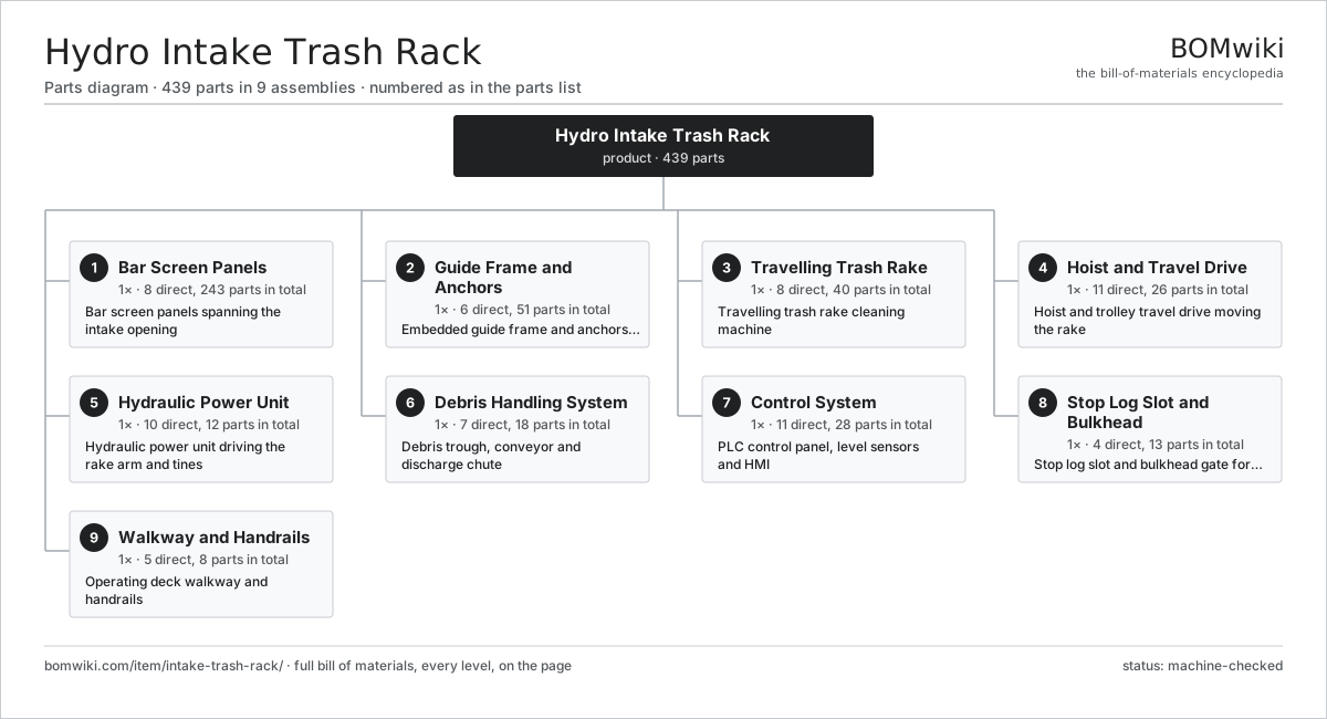
| # | Part | Qty | What it does |
|---|---|---|---|
| 1 | Bar Screen Panels 8 parts | 1× | Bar screen panels spanning the intake opening |
| 2 | Guide Frame and Anchors 6 parts | 1× | Embedded guide frame and anchors set in the intake concrete |
| 3 | Travelling Trash Rake 8 parts | 1× | Travelling trash rake cleaning machine |
| 4 | Hoist and Travel Drive 11 parts | 1× | Hoist and trolley travel drive moving the rake |
| 5 | Hydraulic Power Unit 10 parts | 1× | Hydraulic power unit driving the rake arm and tines |
| 6 | Debris Handling System 7 parts | 1× | Debris trough, conveyor and discharge chute |
| 7 | Control System 11 parts | 1× | PLC control panel, level sensors and HMI |
| 8 | Stop Log Slot and Bulkhead 4 parts | 1× | Stop log slot and bulkhead gate for dewatering |
| 9 | Walkway and Handrails 5 parts | 1× | Operating deck walkway and handrails |
3D model
No 3D model yet. Have a CAD file of this? Add a 3D model — STL renders right on this page; STEP, FreeCAD, and OpenSCAD sources are welcome too (openly licensed, like all 3D models on BOMwiki).
Build & assembly graph
expand / collapse · shared sub-assemblies converge · links to related products · est. labourTap an assembly to expand/collapse · tap a part to open it · use “Open page” for any node · drag to pan, scroll to zoom.
Bill of materials for Hydro Intake Trash Rack
9 top-level lines · 79 rows shown · 439 parts total · indented to 3 levels| # | Item / sub-assembly | Part no. | Qty/assy | Ext. qty | Parts | Type |
|---|---|---|---|---|---|---|
| 1 | Bar Screen Panels 8 parts | intake-trash-rack-screen-panels | 1× | 1 | 243 | assembly |
| 1.1 | Screen Bar | intake-trash-rack-screen-bar | 220× | 220 | · | part |
| 1.2 | Spacer Rod | intake-trash-rack-spacer-rod | 6× | 6 | · | part |
| 1.3 | Side Channel | intake-trash-rack-side-channel | 2× | 2 | · | part |
| 1.4 | Bottom Sill Bar | intake-trash-rack-bottom-sill | 1× | 1 | · | part |
| 1.5 | Top Chord | intake-trash-rack-top-chord | 1× | 1 | · | part |
| 1.6 | Panel Stiffener | intake-trash-rack-panel-stiffener | 8× | 8 | · | part |
| 1.7 | Wear Strip | intake-trash-rack-wear-strip | 4× | 4 | · | part |
| 1.8 | Fastener Set | fastener-set | 1× | 1 | · | part |
| 2 | Guide Frame and Anchors 6 parts | intake-trash-rack-guide-frame | 1× | 1 | 51 | assembly |
| 2.1 | Embedded Guide Rail | intake-trash-rack-embedded-guide | 2× | 2 | · | part |
| 2.2 | Anchor Bolt | intake-trash-rack-anchor-bolt | 32× | 32 | · | part |
| 2.3 | Anchor Plate | intake-trash-rack-anchor-plate | 8× | 8 | · | part |
| 2.4 | Frame Sill Beam | intake-trash-rack-frame-sill | 1× | 1 | · | part |
| 2.5 | Seal Seat Strip | intake-trash-rack-seal-seat | 2× | 2 | · | part |
| 2.6 | Grout Port | intake-trash-rack-grout-port | 6× | 6 | · | part |
| 3 | Travelling Trash Rake 8 parts | intake-trash-rack-rake-machine | 1× | 1 | 40 | assembly |
| 3.1 | Rake Head | intake-trash-rack-rake-head | 1× | 1 | · | part |
| 3.2 | Rake Tine | intake-trash-rack-rake-tine | 24× | 24 | · | part |
| 3.3 | Telescoping Arm | intake-trash-rack-telescoping-arm | 1× | 1 | · | part |
| 3.4 | Arm Cylinder | intake-trash-rack-arm-cylinder | 2× | 2 | · | part |
| 3.5 | Rake Cylinder | intake-trash-rack-rake-cylinder | 1× | 1 | · | part |
| 3.6 | Pivot Pin | intake-trash-rack-pivot-pin | 4× | 4 | · | part |
| 3.7 | Guide Roller | intake-trash-rack-guide-roller | 6× | 6 | · | part |
| 3.8 | Rake Frame | intake-trash-rack-rake-frame | 1× | 1 | · | part |
| 4 | Hoist and Travel Drive 11 parts | intake-trash-rack-hoist-drive | 1× | 1 | 26 | assembly |
| 4.1 | Travel Motor | intake-trash-rack-travel-motor | 1× | 1 | · | part |
| 4.2 | Gearbox Housing | gearbox-housing | 1× | 1 | · | part |
| 4.3 | Helical Gear Pair | gear-pair | 1× | 1 | · | part |
| 4.4 | Hoist Drum | intake-trash-rack-hoist-drum | 1× | 1 | · | part |
| 4.5 | Wire Rope | intake-trash-rack-wire-rope | 2× | 2 | · | part |
| 4.6 | Sheave | intake-trash-rack-sheave | 4× | 4 | · | part |
| 4.7 | Trolley Frame | intake-trash-rack-trolley-frame | 1× | 1 | · | part |
| 4.8 | Travel Wheel | intake-trash-rack-travel-wheel | 4× | 4 | · | part |
| 4.9 | Travel Rail | intake-trash-rack-travel-rail | 2× | 2 | · | part |
| 4.10 | Ball Bearing | ball-bearing | 8× | 8 | · | part |
| 4.11 | Hoist Brake | intake-trash-rack-brake | 1× | 1 | · | part |
| 5 | Hydraulic Power Unit 10 parts | intake-trash-rack-hydraulic-unit | 1× | 1 | 12 | assembly |
| 5.1 | Hydraulic Pump | intake-trash-rack-hpu-pump | 1× | 1 | · | part |
| 5.2 | HPU Motor | intake-trash-rack-hpu-motor | 1× | 1 | · | part |
| 5.3 | Oil Reservoir | intake-trash-rack-hpu-reservoir | 1× | 1 | · | part |
| 5.4 | Valve Block | intake-trash-rack-valve-block | 1× | 1 | · | part |
| 5.5 | Relief Valve | intake-trash-rack-relief-valve | 1× | 1 | · | part |
| 5.6 | Oil Filter | intake-trash-rack-oil-filter | 2× | 2 | · | part |
| 5.7 | Accumulator | intake-trash-rack-accumulator | 1× | 1 | · | part |
| 5.8 | Hydraulic Hose Set | intake-trash-rack-hose-set | 1× | 1 | · | part |
| 5.9 | Pressure Sensor | pressure-sensor | 2× | 2 | · | part |
| 5.10 | O-Ring Set | oring-set | 1× | 1 | · | part |
| 6 | Debris Handling System 7 parts | intake-trash-rack-debris-handling | 1× | 1 | 18 | assembly |
| 6.1 | Debris Trough | intake-trash-rack-debris-trough | 1× | 1 | · | part |
| 6.2 | Conveyor Belt | intake-trash-rack-conveyor-belt | 1× | 1 | · | part |
| 6.3 | Conveyor Roller | intake-trash-rack-conveyor-roller | 12× | 12 | · | part |
| 6.4 | Conveyor Motor | intake-trash-rack-conveyor-motor | 1× | 1 | · | part |
| 6.5 | Discharge Chute | intake-trash-rack-discharge-chute | 1× | 1 | · | part |
| 6.6 | Belt Scraper | intake-trash-rack-scraper | 1× | 1 | · | part |
| 6.7 | Drive Belt | drive-belt | 1× | 1 | · | part |
| 7 | Control System 11 parts | intake-trash-rack-control-system | 1× | 1 | 28 | assembly |
| 7.1 | PLC Panel | intake-trash-rack-plc-panel | 1× | 1 | · | part |
| 7.2 | Upstream Level Sensor | intake-trash-rack-upstream-level | 1× | 1 | · | part |
| 7.3 | Downstream Level Sensor | intake-trash-rack-downstream-level | 1× | 1 | · | part |
| 7.4 | Limit Switch | intake-trash-rack-limit-switch | 6× | 6 | · | part |
| 7.5 | Position Encoder | intake-trash-rack-encoder | 2× | 2 | · | part |
| 7.6 | LCD Panel | lcd-panel | 1× | 1 | · | part |
| 7.7 | Power Supply | power-supply | 1× | 1 | · | part |
| 7.8 | Relay | relay | 8× | 8 | · | part |
| 7.9 | Variable Frequency Drive | intake-trash-rack-vfd | 2× | 2 | · | part |
| 7.10 | Wire Bundle | wire-bundle | 1× | 1 | · | part |
| 7.11 | Connector | connector | 4× | 4 | · | part |
| 8 | Stop Log Slot and Bulkhead 4 parts | intake-trash-rack-stoplog-slot | 1× | 1 | 13 | assembly |
| 8.1 | Stop Log Beam | intake-trash-rack-stoplog-beam | 5× | 5 | · | part |
| 8.2 | Stop Log Seal | intake-trash-rack-stoplog-seal | 5× | 5 | · | part |
| 8.3 | Lifting Beam | intake-trash-rack-lifting-beam | 1× | 1 | · | part |
| 8.4 | Slot Guide | intake-trash-rack-slot-guide | 2× | 2 | · | part |
| 9 | Walkway and Handrails 5 parts | intake-trash-rack-walkway | 1× | 1 | 8 | assembly |
| 9.1 | Deck Grating | intake-trash-rack-deck-grating | 1× | 1 | · | part |
| 9.2 | Handrail | intake-trash-rack-handrail | 1× | 1 | · | part |
| 9.3 | Access Ladder | intake-trash-rack-access-ladder | 1× | 1 | · | part |
| 9.4 | Support Beam | intake-trash-rack-support-beam | 4× | 4 | · | part |
| 9.5 | Fastener Set | fastener-set | 1× | 1 | · | part |
Related products
same domain, ranked by shared parts Wind Turbine
28,312 parts · shares 7 with this page
Wind Turbine
28,312 parts · shares 7 with this page
 Wind Turbine Nacelle
287 parts · shares 7 with this page
Biomass Pellet Boiler
139 parts · shares 5 with this page
Wind Turbine Nacelle
287 parts · shares 7 with this page
Biomass Pellet Boiler
139 parts · shares 5 with this page
 Biomass Pellet Plant
404 parts · shares 5 with this page
Biomass Pellet Plant
404 parts · shares 5 with this page
 Floating Offshore Wind Turbine
608 parts · shares 5 with this page
Floating Offshore Wind Turbine
608 parts · shares 5 with this page
Sourcing: possible vendors
Prices, MOQ, and lead times are algorithmic estimates, not quotes, and not claims about these companies. Company mappings are curated by keyword; est. price band $100–$20M. How estimates work| Vendor | HQ | Specialty | MOQ | Lead time |
|---|---|---|---|---|
|
🇩🇰Vestas
vestas.com ↗
|
Aarhus, DK | Wind turbines | 500 units | 12–24 wks |
| firstsolar.com ↗ | Tempe, US | PV modules | 500 units | 12–24 wks |
|
🇨🇳LONGi
longi.com ↗
|
Xi'an, CN | Solar wafers & modules | 500 units | 12–24 wks |
| enphase.com ↗ | Fremont, US | Microinverters & storage | 500 units | 12–24 wks |
|
🇨🇳Sungrow
sungrowpower.com ↗
|
Hefei, CN | Solar inverters & storage | 500 units | 12–24 wks |
1,055-word article