Wind Turbine Gearbox
ProductOverview
A wind turbine gearbox is a step-up transmission that bridges a mismatch between the rotor and the generator. The rotor turns slowly, around 10 to 15 revolutions per minute, with enormous torque, while a standard generator wants to spin near 1500 rpm with far less torque. The gearbox multiplies the speed by roughly a hundred to one and divides the torque by the same factor. It is one of the most stressed parts of a turbine because it carries the full power, typically in the 2 to 6 megawatt class, through gear teeth that must survive 20 years of gusting, variable load.
The unit is built in three gear stages plus the systems that keep them running. The Planetary Stage is the low-speed first stage, followed by the Intermediate Stage and the High-Speed Stage helical pairs. The Housing Set holds everything and the oil, the Lubrication System feeds and cools the gears, the Mounting System ties the gearbox to the bedplate, the Condition Monitoring pack watches for damage, and the Generator Coupling passes torque to the generator.
Planetary first stage
The rotor connects to the Planetary Stage, chosen for the first stage because it splits the huge input torque across several gear meshes at once. The slow rotor drives the Planet Carrier, which holds three Planet Gear gears on their Planet Pin pins. As the carrier turns, each planet rolls inside the fixed Ring Gear and spins the central Sun Gear much faster. Because three planets share the load, each tooth and each Planet Bearing sees only a third of the torque, which is what lets a compact stage handle megawatt power. The gears are cut from case-hardened 18CrNiMo7-6 steel and ground for accuracy so the load spreads evenly across the tooth face.
Helical stages
The fast-spinning sun gear feeds the Intermediate Stage, a parallel Helical Gear Pair of helical gears on the Intermediate Shaft, supported on Ball Bearing bearings with Oil Seal seals. This stage steps the speed up again. From there the High-Speed Stage takes over with another helical Helical Gear Pair on the High-Speed Shaft, the fastest and hottest shaft in the box, so it runs on Taper Roller Bearing taper rollers that take combined load. A Shrink Disc clamps the coupling to the output without a keyway. Helical teeth are used in these stages because their angled contact engages gradually, which runs far quieter and smoother than straight-cut teeth at these speeds.
Housing and structure
All three stages bolt into the Housing Set, a split cast iron casing. The Front Housing Half half carries the planetary stage and the ring gear, while the Rear Housing Half half carries the high-speed bearings, with a Gearbox Housing center section between them. Each shaft end is closed by a Bearing End Cover, and the case is sealed with an O-Ring Set and held by Fastener Set through-bolts. An Inspection Cover lets a technician borescope the gear teeth in the field without splitting the housing, which matters because the gearbox sits in a nacelle a hundred metres up where major teardown is expensive.
Lubrication and cooling
A wind gearbox cannot run dry or hot for long, so the Lubrication System is as important as the gears. The Lube Oil Pump pulls Synthetic Gear Oil, a high-viscosity synthetic lubricant, from the sump and pushes it through an Oil Filter and the Oil Cooler, then to the Oil Spray Manifold that sprays metered oil onto every mesh and bearing. In cold climates an Oil Heater warms the charge before start so the oil actually flows, and Pressure Sensor gauges confirm the loop is healthy before the turbine takes load. The lubricant does two jobs at once: it builds the thin film that keeps steel teeth from touching, and it carries away the heat generated at the contacts.
Mounting, monitoring, and output
The gearbox is held by the Mounting System, where two Torque Arm arms react the gearbox torque into the bedplate through Elastomer Bushing bushings and Trunnion Pin pins. The soft bushings let the drivetrain flex and absorb shock instead of cracking the housing. Because a gearbox failure means a crane and days of downtime, the Condition Monitoring pack watches continuously: Vibration Sensor accelerometers at each bearing reveal gear and bearing defects in their vibration spectrum, an Oil Particle Sensor counts wear debris, and Temperature Sensor probes flag overheating, all read by a Monitoring Board over a Wire Bundle. Finally the Generator Coupling connects to the generator through Flexible Element flexible discs and an insulating Spacer Tube, with a Torque Limiter that slips during a generator fault to protect the whole drivetrain.
Wind Turbine Gearbox parts and their functions
8 top-level parts · 172 parts in total · full bill of materials below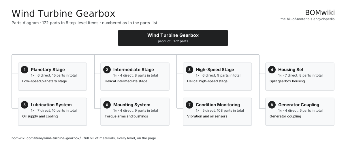
| # | Part | Qty | What it does |
|---|---|---|---|
| 1 | Planetary Stage 6 parts | 1× | Low-speed planetary stage |
| 2 | Intermediate Stage 4 parts | 1× | Helical intermediate stage |
| 3 | High-Speed Stage 6 parts | 1× | Helical high-speed stage |
| 4 | Housing Set 7 parts | 1× | Split gearbox housing |
| 5 | Lubrication System 7 parts | 1× | Oil supply and cooling |
| 6 | Mounting System 4 parts | 1× | Torque arms and bushings |
| 7 | Condition Monitoring 5 parts | 1× | Vibration and oil sensors |
| 8 | Generator Coupling 4 parts | 1× | Generator coupling |
3D model
No 3D model yet. Have a CAD file of this? Add a 3D model. STL renders right on this page; STEP, FreeCAD, and OpenSCAD sources are welcome too (openly licensed, like all 3D models on BOMwiki).
Build & assembly graph
expand / collapse · shared sub-assemblies converge · links to related products · est. labourTap an assembly to expand/collapse · tap a part to open it · use “Open page” for any node · drag to pan, scroll to zoom.
Bill of materials for Wind Turbine Gearbox
8 top-level lines · 57 rows shown · 172 parts total · indented to 3 levels| # | Item / sub-assembly | Part no. | Qty/assy | Ext. qty | Parts | Type |
|---|---|---|---|---|---|---|
| 1 | Planetary Stage 6 parts | wtg-planetary-stage | 1× | 1 | 15 | assembly |
| 1.1 | Planet Carrier | wtg-planet-carrier | 1× | 1 | · | part |
| 1.2 | Planet Gear | wtg-planet-gear | 3× | 3 | · | part |
| 1.3 | Ring Gear | wtg-ring-gear | 1× | 1 | · | part |
| 1.4 | Sun Gear | wtg-sun-gear | 1× | 1 | · | part |
| 1.5 | Planet Bearing | wtg-planet-bearing | 6× | 6 | · | part |
| 1.6 | Planet Pin | wtg-planet-pin | 3× | 3 | · | part |
| 2 | Intermediate Stage 4 parts | wtg-intermediate-stage | 1× | 1 | 8 | assembly |
| 2.1 | Helical Gear Pair | gear-pair | 1× | 1 | · | part |
| 2.2 | Intermediate Shaft | wtg-intermediate-shaft | 1× | 1 | · | part |
| 2.3 | Ball Bearing | ball-bearing | 4× | 4 | · | part |
| 2.4 | Oil Seal | oil-seal | 2× | 2 | · | part |
| 3 | High-Speed Stage 6 parts | wtg-highspeed-stage | 1× | 1 | 9 | assembly |
| 3.1 | Helical Gear Pair | gear-pair | 1× | 1 | · | part |
| 3.2 | High-Speed Shaft | wtg-highspeed-shaft | 1× | 1 | · | part |
| 3.3 | Taper Roller Bearing | wtg-taper-bearing | 2× | 2 | · | part |
| 3.4 | Ball Bearing | ball-bearing | 2× | 2 | · | part |
| 3.5 | Oil Seal | oil-seal | 2× | 2 | · | part |
| 3.6 | Shrink Disc | wtg-shrink-disc | 1× | 1 | · | part |
| 4 | Housing Set 7 parts | wtg-housing-set | 1× | 1 | 8 | assembly |
| 4.1 | Front Housing Half | wtg-housing-front | 1× | 1 | · | part |
| 4.2 | Rear Housing Half | wtg-housing-rear | 1× | 1 | · | part |
| 4.3 | Gearbox Housing | gearbox-housing | 1× | 1 | · | part |
| 4.4 | Bearing End Cover | wtg-end-cover | 2× | 2 | · | part |
| 4.5 | O-Ring Set | oring-set | 1× | 1 | · | part |
| 4.6 | Fastener Set | fastener-set | 1× | 1 | · | part |
| 4.7 | Inspection Cover | wtg-inspection-cover | 1× | 1 | · | part |
| 5 | Lubrication System 7 parts | wtg-lubrication-system | 1× | 1 | 10 | assembly |
| 5.1 | Lube Oil Pump | wtg-oil-pump | 1× | 1 | · | part |
| 5.2 | Oil Cooler | wtg-oil-cooler | 1× | 1 | · | part |
| 5.3 | Oil Filter | wtg-oil-filter | 2× | 2 | · | part |
| 5.4 | Oil Spray Manifold | wtg-oil-manifold | 1× | 1 | · | part |
| 5.5 | Oil Heater 2 parts | wtg-oil-heater | 1× | 1 | 2 | assembly |
| 5.5.1 | Heating Element | heating-element | 1× | 1 | · | part |
| 5.5.2 | Pressure Sensor | pressure-sensor | 1× | 1 | · | part |
| 5.6 | Synthetic Gear Oil | wtg-gear-oil | 1× | 1 | · | part |
| 5.7 | Pressure Sensor | pressure-sensor | 2× | 2 | · | part |
| 6 | Mounting System 4 parts | wtg-mounting-system | 1× | 1 | 9 | assembly |
| 6.1 | Torque Arm | wtg-torque-arm | 2× | 2 | · | part |
| 6.2 | Elastomer Bushing | wtg-elastomer-bush | 4× | 4 | · | part |
| 6.3 | Trunnion Pin | wtg-trunnion-pin | 2× | 2 | · | part |
| 6.4 | Fastener Set | fastener-set | 1× | 1 | · | part |
| 7 | Condition Monitoring 5 parts | wtg-condition-monitoring | 1× | 1 | 108 | assembly |
| 7.1 | Vibration Sensor | wtg-vibration-sensor | 6× | 6 | · | part |
| 7.2 | Oil Particle Sensor | wtg-oil-particle-sensor | 1× | 1 | · | part |
| 7.3 | Temperature Sensor | wtg-temp-sensor | 4× | 4 | · | part |
| 7.4 | Monitoring Board 4 parts | wtg-cms-board | 1× | 1 | 96 | assembly |
| 7.4.1 | Bare PCB | pcb-bare | 1× | 1 | · | part |
| 7.4.2 | Microcontroller | mcu | 1× | 1 | · | part |
| 7.4.3 | SMD Passive (R/C/L) | smd-passives | 90× | 90 | · | part |
| 7.4.4 | Connector | connector | 4× | 4 | · | part |
| 7.5 | Wire Bundle | wire-bundle | 1× | 1 | · | part |
| 8 | Generator Coupling 4 parts | wtg-coupling | 1× | 1 | 5 | assembly |
| 8.1 | Flexible Element | wtg-flex-element | 2× | 2 | · | part |
| 8.2 | Spacer Tube | wtg-spacer-tube | 1× | 1 | · | part |
| 8.3 | Torque Limiter | wtg-torque-limiter | 1× | 1 | · | part |
| 8.4 | Fastener Set | fastener-set | 1× | 1 | · | part |
Something wrong in this list? Report a problem with this BOM.
Related products
same domain, ranked by shared parts Wind Turbine
28,312 parts · shares 7 with this page
 Wind Turbine Nacelle
287 parts · shares 7 with this page
Biomass Pellet Boiler
139 parts · shares 5 with this page
 Concentrated Solar Power Receiver
855 parts · shares 6 with this page
Wind Turbine Yaw Drive
1,216 parts · shares 6 with this page
 Biomass Pellet Plant
404 parts · shares 5 with this page
Sourcing: possible vendors
Browse the supplier directory → Prices, MOQ, and lead times are algorithmic estimates, not quotes, and not claims about these companies. Company mappings are curated by keyword; est. price band $100–$20M. How estimates work| Vendor | HQ | Specialty | MOQ | Lead time |
|---|---|---|---|---|
|
🇩🇰Vestas
vestas.com ↗
|
Aarhus, DK | Wind turbines | 500 units | 12–24 wks |
| firstsolar.com ↗ | Tempe, US | PV modules | 500 units | 12–24 wks |
|
🇨🇳LONGi
longi.com ↗
|
Xi'an, CN | Solar wafers & modules | 500 units | 12–24 wks |
| enphase.com ↗ | Fremont, US | Microinverters & storage | 500 units | 12–24 wks |
|
🇨🇳Sungrow
sungrowpower.com ↗
|
Hefei, CN | Solar inverters & storage | 500 units | 12–24 wks |
815-word article