Blast Hole Stemming Loader
ProductOverview
After a blast hole is drilled and charged with explosive, the top portion of the hole is filled with inert material called stemming. Stemming is what makes the explosive do useful work. Without it, the expanding gases from detonation take the path of least resistance and blow straight up out of the collar, producing a loud, dangerous, and largely wasted blast. A well-placed column of crushed aggregate confines those gases long enough for the shock to fracture and heave the rock. The blast hole stemming loader is the machine that places this material quickly, consistently, and without sending people to walk a charged pattern with shovels.
The machine is a self-propelled aggregate handler. A Truck Chassis and Cab carries a Stemming Hopper of crushed rock across the bench. A Vibrating Feeder draws material out, a Discharge Conveyor lifts it, a Metering Gate gate controls the flow, and a Discharge Boom boom drops a measured volume neatly into each hole. The whole sequence is run by one operator from the cab, which keeps personnel out of the charged area.
Why stemming matters
The quality of stemming directly affects blast performance and safety. The material should be angular crushed rock rather than rounded gravel or drill cuttings, because angular particles interlock and resist being ejected. The right size is roughly one tenth of the hole diameter, large enough to wedge but small enough to flow. Too little stemming, or stemming that is too fine, leads to stemming ejection: the column shoots out, gas escapes early, and the blast produces flyrock, excessive noise, and poor fragmentation. A loader that meters a consistent column length to every hole removes a large source of variability in the blast, which is why mines increasingly weigh and record what each hole receives.
Chassis and mobility
The Truck Chassis and Cab is an off-highway truck sized to carry the laden hopper across rough bench surfaces. A diesel Diesel Engine drives the wheels through a Powershift Transmission and powers the plant through a Power Take-Off. The drive Drive Axle units use planetary final drives and large Off-Highway Tire units to handle the loose, broken ground of a recently drilled pattern. The Operator Cab gives the operator a clear view of the hole collars and an in-cab display of the metering system.
Hopper and feeder
Crushed aggregate is held in the Stemming Hopper, lined throughout with abrasion-resistant plate because the material is hard and constantly moving against the walls. A Grizzly Screen bar screen across the top rejects any oversize rock that would jam the spout. At the bottom, a Vibrating Feeder of the vibrating-pan type draws material out at a controlled rate; the eccentric Vibrator Motor keeps the aggregate flowing and prevents it from bridging over the outlet. The hopper sits on Load Cell units so the machine knows by weight exactly how much it has dispensed.
Conveying and metering
A Discharge Conveyor lifts the aggregate from the feeder up to discharge height. It is a reinforced belt running on Idler Roller rollers between a drive and tail Conveyor Pulley, turned by a hydraulic Conveyor Motor. The flow per hole is set by the Metering Gate gate, a hardened Slide Gate driven by a Gate Cylinder. Combining the gate opening with the weighed hopper reading lets the control system deliver a target mass or volume to each hole and stop cleanly when it is reached.
Positioning over the hole
The Discharge Boom is what makes the machine accurate. An articulated Boom Arm, moved by Boom Cylinder units, swings a telescoping Discharge Spout out over the pattern. A Hole Locator cone centers the spout on the collar so the aggregate drops cleanly into the hole rather than spilling onto the bench. Because the operator can reach several holes from one machine position, the loader can stem a row at a time without repositioning for every hole, which is where most of its productivity advantage over hand stemming comes from.
Hydraulics, control, and variants
The Hydraulic System system, driven from the PTO, powers the feeder, conveyor, gate, and boom. The Control System system, built around a Plant Controller, reads the load cells and gate position, meters each charge, and logs the volume placed in every hole for the blast record. Variants scale with the operation. Large surface mines use machines with big hoppers and long booms matched to large-diameter holes and wide patterns. Quarries and construction blasting use smaller, more maneuverable units. Some designs combine stemming with the placement of stemming plugs or gas bags that further improve confinement, and others integrate with the drill rig's hole-position data so the boom can find each collar with less operator input.
Blast Hole Stemming Loader parts and their functions
7 top-level parts · 198 parts in total · full bill of materials below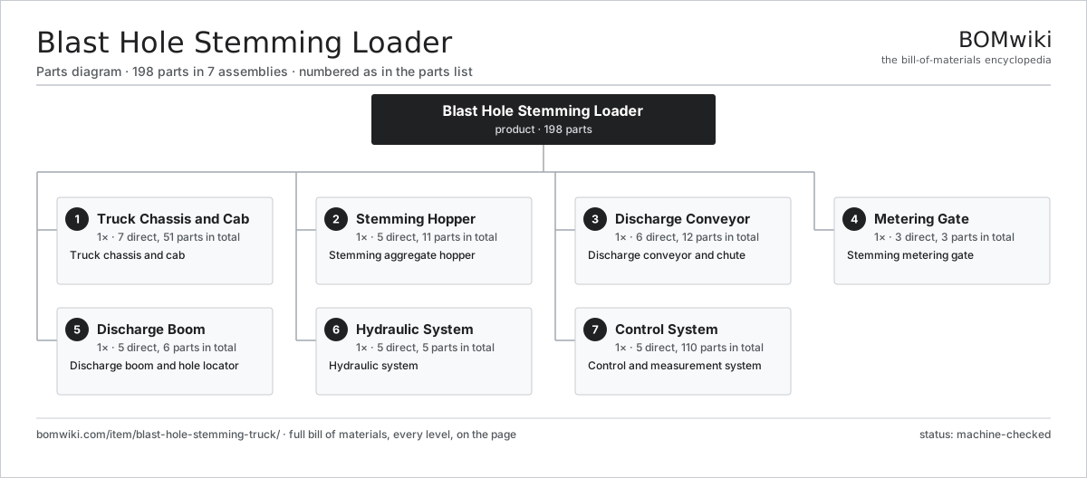
| # | Part | Qty | What it does |
|---|---|---|---|
| 1 | Truck Chassis and Cab 7 parts | 1× | Truck chassis and cab |
| 2 | Stemming Hopper 5 parts | 1× | Stemming aggregate hopper |
| 3 | Discharge Conveyor 6 parts | 1× | Discharge conveyor and chute |
| 4 | Metering Gate 3 parts | 1× | Stemming metering gate |
| 5 | Discharge Boom 5 parts | 1× | Discharge boom and hole locator |
| 6 | Hydraulic System 5 parts | 1× | Hydraulic system |
| 7 | Control System 5 parts | 1× | Control and measurement system |
3D model
No 3D model yet. Have a CAD file of this? Add a 3D model — STL renders right on this page; STEP, FreeCAD, and OpenSCAD sources are welcome too (openly licensed, like all 3D models on BOMwiki).
Build & assembly graph
expand / collapse · shared sub-assemblies converge · links to related products · est. labourTap an assembly to expand/collapse · tap a part to open it · use “Open page” for any node · drag to pan, scroll to zoom.
Bill of materials for Blast Hole Stemming Loader
7 top-level lines · 68 rows shown · 198 parts total · indented to 3 levels| # | Item / sub-assembly | Part no. | Qty/assy | Ext. qty | Parts | Type |
|---|---|---|---|---|---|---|
| 1 | Truck Chassis and Cab 7 parts | blast-hole-stemming-truck-chassis | 1× | 1 | 51 | assembly |
| 1.1 | Chassis Frame | blast-hole-stemming-truck-frame | 1× | 1 | · | part |
| 1.2 | Diesel Engine 5 parts | blast-hole-stemming-truck-engine | 1× | 1 | 7 | assembly |
| 1.2.1 | Engine Block | blast-hole-stemming-truck-engine-block | 1× | 1 | · | part |
| 1.2.2 | Turbocharger | blast-hole-stemming-truck-turbo | 1× | 1 | · | part |
| 1.2.3 | Radiator | blast-hole-stemming-truck-radiator | 1× | 1 | · | part |
| 1.2.4 | Oil Seal | oil-seal | 3× | 3 | · | part |
| 1.2.5 | Fastener Set | fastener-set | 1× | 1 | · | part |
| 1.3 | Powershift Transmission 4 parts | blast-hole-stemming-truck-transmission | 1× | 1 | 10 | assembly |
| 1.3.1 | Helical Gear Pair | gear-pair | 2× | 2 | · | part |
| 1.3.2 | Gearbox Housing | gearbox-housing | 1× | 1 | · | part |
| 1.3.3 | Ball Bearing | ball-bearing | 4× | 4 | · | part |
| 1.3.4 | Oil Seal | oil-seal | 3× | 3 | · | part |
| 1.4 | Drive Axle 5 parts | blast-hole-stemming-truck-axle | 2× | 2 | 12 | assembly |
| 1.4.1 | Axle Housing | blast-hole-stemming-truck-axle-housing | 1× | 2 | · | part |
| 1.4.2 | Helical Gear Pair | gear-pair | 1× | 2 | · | part |
| 1.4.3 | Service Brake | blast-hole-stemming-truck-brake | 2× | 4 | · | part |
| 1.4.4 | Ball Bearing | ball-bearing | 4× | 8 | · | part |
| 1.4.5 | Oil Seal | oil-seal | 4× | 8 | · | part |
| 1.5 | Off-Highway Tire | blast-hole-stemming-truck-tire | 4× | 4 | · | part |
| 1.6 | Operator Cab 4 parts | blast-hole-stemming-truck-cab | 1× | 1 | 4 | assembly |
| 1.6.1 | Cab Shell | blast-hole-stemming-truck-cab-shell | 1× | 1 | · | part |
| 1.6.2 | Operator Seat | blast-hole-stemming-truck-seat | 1× | 1 | · | part |
| 1.6.3 | LCD Panel | lcd-panel | 1× | 1 | · | part |
| 1.6.4 | Cab Climate Unit | blast-hole-stemming-truck-hvac | 1× | 1 | · | part |
| 1.7 | Power Take-Off | blast-hole-stemming-truck-pto | 1× | 1 | · | part |
| 2 | Stemming Hopper 5 parts | blast-hole-stemming-truck-hopper | 1× | 1 | 11 | assembly |
| 2.1 | Hopper Body | blast-hole-stemming-truck-hopper-body | 1× | 1 | · | part |
| 2.2 | Hopper Liner | blast-hole-stemming-truck-hopper-liner | 1× | 1 | · | part |
| 2.3 | Vibrating Feeder 3 parts | blast-hole-stemming-truck-feeder | 1× | 1 | 6 | assembly |
| 2.3.1 | Feeder Pan | blast-hole-stemming-truck-feeder-pan | 1× | 1 | · | part |
| 2.3.2 | Vibrator Motor | blast-hole-stemming-truck-vibrator | 1× | 1 | · | part |
| 2.3.3 | Coil Spring | coil-spring | 4× | 4 | · | part |
| 2.4 | Grizzly Screen | blast-hole-stemming-truck-grizzly | 1× | 1 | · | part |
| 2.5 | Load Cell | blast-hole-stemming-truck-load-cell | 2× | 2 | · | part |
| 3 | Discharge Conveyor 6 parts | blast-hole-stemming-truck-conveyor | 1× | 1 | 12 | assembly |
| 3.1 | Conveyor Belt | blast-hole-stemming-truck-belt | 1× | 1 | · | part |
| 3.2 | Conveyor Frame | blast-hole-stemming-truck-conveyor-frame | 1× | 1 | · | part |
| 3.3 | Conveyor Pulley | blast-hole-stemming-truck-pulley | 2× | 2 | · | part |
| 3.4 | Conveyor Motor | blast-hole-stemming-truck-conveyor-motor | 1× | 1 | · | part |
| 3.5 | Idler Roller | blast-hole-stemming-truck-idler | 6× | 6 | · | part |
| 3.6 | Discharge Chute | blast-hole-stemming-truck-chute | 1× | 1 | · | part |
| 4 | Metering Gate 3 parts | blast-hole-stemming-truck-metering | 1× | 1 | 3 | assembly |
| 4.1 | Slide Gate | blast-hole-stemming-truck-gate | 1× | 1 | · | part |
| 4.2 | Gate Cylinder | blast-hole-stemming-truck-gate-cylinder | 1× | 1 | · | part |
| 4.3 | Flow Sensor | blast-hole-stemming-truck-flow-sensor | 1× | 1 | · | part |
| 5 | Discharge Boom 5 parts | blast-hole-stemming-truck-positioner | 1× | 1 | 6 | assembly |
| 5.1 | Boom Arm | blast-hole-stemming-truck-boom-arm | 1× | 1 | · | part |
| 5.2 | Boom Cylinder | blast-hole-stemming-truck-boom-cylinder | 2× | 2 | · | part |
| 5.3 | Discharge Spout | blast-hole-stemming-truck-spout | 1× | 1 | · | part |
| 5.4 | Hole Locator | blast-hole-stemming-truck-hole-locator | 1× | 1 | · | part |
| 5.5 | Ball Bearing | ball-bearing | 1× | 1 | · | part |
| 6 | Hydraulic System 5 parts | blast-hole-stemming-truck-hydraulic | 1× | 1 | 5 | assembly |
| 6.1 | Hydraulic Pump | blast-hole-stemming-truck-hyd-pump | 1× | 1 | · | part |
| 6.2 | Hydraulic Reservoir | blast-hole-stemming-truck-hyd-tank | 1× | 1 | · | part |
| 6.3 | Valve Bank | blast-hole-stemming-truck-valve-bank | 1× | 1 | · | part |
| 6.4 | Oil Cooler | blast-hole-stemming-truck-hyd-cooler | 1× | 1 | · | part |
| 6.5 | Hydraulic Filter | blast-hole-stemming-truck-hyd-filter | 1× | 1 | · | part |
| 7 | Control System 5 parts | blast-hole-stemming-truck-control | 1× | 1 | 110 | assembly |
| 7.1 | Plant Controller 4 parts | blast-hole-stemming-truck-controller | 1× | 1 | 88 | assembly |
| 7.1.1 | Bare PCB | pcb-bare | 1× | 1 | · | part |
| 7.1.2 | Microcontroller | mcu | 1× | 1 | · | part |
| 7.1.3 | SMD Passive (R/C/L) | smd-passives | 80× | 80 | · | part |
| 7.1.4 | Connector | connector | 6× | 6 | · | part |
| 7.2 | LCD Panel | lcd-panel | 1× | 1 | · | part |
| 7.3 | Wire Bundle | wire-bundle | 1× | 1 | · | part |
| 7.4 | Connector | connector | 14× | 14 | · | part |
| 7.5 | Relay | relay | 6× | 6 | · | part |
Related products
same domain, ranked by shared parts Electric Rope Shovel
507 parts · shares 4 with this page
Mechanized Scaling Rig
530 parts · shares 4 with this page
Electric Rope Shovel
507 parts · shares 4 with this page
Mechanized Scaling Rig
530 parts · shares 4 with this page
 Mineral Jig Concentrator
145 parts · shares 4 with this page
Raise Climber Platform
447 parts · shares 4 with this page
Double Roll Crusher
214 parts · shares 2 with this page
Bulk Explosive Charging Truck
229 parts · shares 3 with this page
Mineral Jig Concentrator
145 parts · shares 4 with this page
Raise Climber Platform
447 parts · shares 4 with this page
Double Roll Crusher
214 parts · shares 2 with this page
Bulk Explosive Charging Truck
229 parts · shares 3 with this page
Sourcing: possible vendors
Prices, MOQ, and lead times are algorithmic estimates, not quotes, and not claims about these companies. Company mappings are curated by keyword; est. price band $200k–$5M. How estimates work| Vendor | HQ | Specialty | MOQ | Lead time |
|---|---|---|---|---|
| caterpillar.com ↗ | Irving, US | Construction & mining equipment | made to order | 20–36 wks |
|
🇯🇵Komatsu
komatsu.com ↗
|
Tokyo, JP | Construction & mining equipment | made to order | 20–36 wks |
|
🇸🇪Sandvik
rocktechnology.sandvik ↗
|
Stockholm, SE | Mining & rock technology | made to order | 20–36 wks |
|
🇸🇪Epiroc
epiroc.com ↗
|
Stockholm, SE | Mining & drilling equipment | made to order | 20–36 wks |
|
🇫🇮Metso
metso.com ↗
|
Helsinki, FI | Crushing & minerals processing | made to order | 20–36 wks |
889-word article