Raise Climber Platform
ProductOverview
A raise climber is a rail-guided platform that carries miners up the face of a raise so they can drill, charge and blast it from below. A raise is a near-vertical or steeply inclined opening driven upward between two levels of a mine, used for ventilation, ore passes or as the start of a stope. Driving one by hand is slow and exposes the crew to rock falling from the face above them. The raise climber solves both problems: it rides a toothed Rack Rail Section bolted to the wall, lifts the crew to the face on a protected Working Platform, and lowers them clear before each blast. The best known examples are the Alimak raise climbers, and the design has become the standard method for conventional raise driving.
The machine has a handful of cooperating subsystems: the rack rail and its anchors, the Climbing Drive Unit that climbs the rail, the working platform with its Protective Roof Canopy, the Overspeed Safety Brake, the Guide Roller Set that hold it on track, and the Service Lines that feed air, water and ventilation up to the face.
The rack rail and how it climbs
The platform climbs a fixed rail rather than a rope, which is what makes it safe in a steep, irregular bore. Each Rack Rail Section section pairs a structural Rail Profile with a Toothed Rack Bar, a hardened toothed bar machined to a module 8 spur profile. Sections are bolted end to end as the raise advances and fixed to the wall through a Wall Mounting Bracket held by grouted Rock Anchor Bolt bolts. Climbing is done by the Climbing Drive Unit. A Drive Motor turns a Reduction Gearbox which spins the Drive Pinion gears on a Pinion Shaft; those pinions mesh with the rack and walk the platform up or down the rail. Because the pinion is positively engaged with the rack at every point, the platform cannot run away even if power is lost, which is the central safety advantage over a winch-hoisted cage.
The drive motor is offered in three forms to suit the mine. Compressed air suits gassy or wet headings where electrical equipment is restricted, an electric motor gives the highest efficiency on a long pull, and a hydraulic motor delivers high torque in a compact housing. All three feed the same gearbox, whose Helical Gear Pair sets run inside a sealed Gearbox Housing on Ball Bearing supports and shed heat through Gear Oil.
Working platform
The crew works from the Working Platform, a deck framed from a welded Platform Frame and floored with Deck Plate. A Handrail Section guards every edge. Two Folding Deck Wing wings fold inward on a Fold Cylinder so the platform can pass narrow points in the raise, then open out to give the crew room to reach the full face. A pair of Drill Support Rest supports brace the handheld rock drills against the rock so an operator can hold a hole on line while the drill bores into the face overhead.
Protection against rock falls
Working under a freshly blasted face means loose rock can come down at any time, so protection is built into the structure. The Protective Roof Canopy is a Canopy Plate on a Canopy Frame meeting ISO 3449 falling-object standards, and it sits on Coil Spring mounts at each Canopy Mount Bracket so an impact is absorbed rather than transmitted straight into the platform.
The most important safety device is the Overspeed Safety Brake. A Brake Pinion runs continuously on the rack and drives a Centrifugal Governor. If the platform ever descends faster than its rated speed, the Governor Flyweight masses in the governor fly outward against their Coil Spring return and trip a Brake Pawl, which clamps a Brake Disc and grips the rack to bring the platform to a controlled stop. This overspeed brake acts independently of the main drive, so a gearbox or motor failure cannot defeat it.
Guidance and services
Side loads from the platform and from drilling are taken by the Guide Roller Set. Each Guide Roller runs on Ball Bearing supports against the rail profile, and a Roller Adjuster Screw screw sets the running clearance so the platform tracks cleanly without binding. Up the rail run the Service Lines: a Compressed Air Line for the drills, a Water Line for flushing and dust control, and a Ventilation Duct that delivers fresh air to the dead-end face. Slack hose is managed on a Hose Storage Reel, and flow is set with Service Control Valve valves and watched by a Pressure Sensor.
Materials and control
The machine lives in a wet, abrasive setting, so the rack and pinions are made from case-hardened steels in the 17CrNiMo6 to 42CrMo4 range, the structure is S355 plate, and rotating joints are sealed with Oil Seal and O-Ring Set elements. The operator drives from the Control Station, working a set of Control Lever controls through a Control Panel Box of Pilot Valve units, with Emergency Stop Button buttons within reach and a Control PCB Module supervising the interlocks.
Use and variants
A typical cycle has the crew climb to the face, drill the round, descend, then charge and blast from a safe point below before mucking the broken rock down the raise. Climbers are configured for the raise: short rigs for service raises, long electric units for raises reaching 200 m, and air-driven versions for headings where ignition risk rules out electric drives. The method drives raises far faster and more safely than hand mining, which is why it remains standard practice.
Raise Climber Platform parts and their functions
8 top-level parts · 447 parts in total · full bill of materials below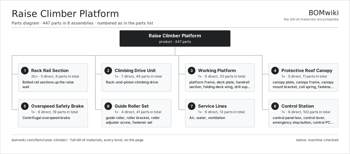
| # | Part | Qty | What it does |
|---|---|---|---|
| 1 | Rack Rail Section 5 parts | 20× | Bolted rail sections up the raise wall |
| 2 | Climbing Drive Unit 7 parts | 1× | Rack-and-pinion climbing drive |
| 3 | Working Platform 6 parts | 1× | Deck where miners stand to drill and charge the face. |
| 4 | Protective Roof Canopy 5 parts | 1× | Steel roof shielding the crew from loose rock above. |
| 5 | Overspeed Safety Brake 6 parts | 1× | Centrifugal overspeed brake |
| 6 | Guide Roller Set 4 parts | 1× | Rollers that keep the platform tracking the rail under side loads. |
| 7 | Service Lines 6 parts | 1× | Air, water, ventilation |
| 8 | Control Station 6 parts | 1× | Lever station the operator uses to raise and lower the platform. |
3D model
No 3D model yet. Have a CAD file of this? Add a 3D model — STL renders right on this page; STEP, FreeCAD, and OpenSCAD sources are welcome too (openly licensed, like all 3D models on BOMwiki).
Build & assembly graph
expand / collapse · shared sub-assemblies converge · links to related products · est. labourTap an assembly to expand/collapse · tap a part to open it · use “Open page” for any node · drag to pan, scroll to zoom.
Bill of materials for Raise Climber Platform
8 top-level lines · 84 rows shown · 447 parts total · indented to 3 levels| # | Item / sub-assembly | Part no. | Qty/assy | Ext. qty | Parts | Type |
|---|---|---|---|---|---|---|
| 1 | Rack Rail Section 5 parts | raise-climber-rack-rail | 20× | 20 | 9 | assembly |
| 1.1 | Rail Profile | raise-climber-rail-profile | 1× | 20 | · | part |
| 1.2 | Toothed Rack Bar | raise-climber-rack-bar | 1× | 20 | · | part |
| 1.3 | Wall Mounting Bracket | raise-climber-wall-bracket | 2× | 40 | · | part |
| 1.4 | Rock Anchor Bolt | raise-climber-rock-anchor | 4× | 80 | · | part |
| 1.5 | Fastener Set | fastener-set | 1× | 20 | · | part |
| 2 | Climbing Drive Unit 7 parts | raise-climber-drive-unit | 1× | 1 | 49 | assembly |
| 2.1 | Drive Motor 5 parts | raise-climber-drive-motor | 1× | 1 | 27 | assembly |
| 2.1.1 | Stator Assembly 3 parts + deeper › | stator-assembly | 1× | 1 | 3 | assembly |
| 2.1.2 | Rotor Assembly 4 parts + deeper › | rotor-assembly | 1× | 1 | 19 | assembly |
| 2.1.3 | Motor Housing | raise-climber-motor-housing | 1× | 1 | · | part |
| 2.1.4 | Ball Bearing | ball-bearing | 2× | 2 | · | part |
| 2.1.5 | Oil Seal | oil-seal | 2× | 2 | · | part |
| 2.2 | Reduction Gearbox 5 parts | raise-climber-drive-gearbox | 1× | 1 | 10 | assembly |
| 2.2.1 | Helical Gear Pair | gear-pair | 2× | 2 | · | part |
| 2.2.2 | Gearbox Housing | gearbox-housing | 1× | 1 | · | part |
| 2.2.3 | Ball Bearing | ball-bearing | 4× | 4 | · | part |
| 2.2.4 | Oil Seal | oil-seal | 2× | 2 | · | part |
| 2.2.5 | Gear Oil | raise-climber-gear-oil | 1× | 1 | · | part |
| 2.3 | Drive Pinion | raise-climber-drive-pinion | 2× | 2 | · | part |
| 2.4 | Pinion Shaft | raise-climber-pinion-shaft | 1× | 1 | · | part |
| 2.5 | Ball Bearing | ball-bearing | 4× | 4 | · | part |
| 2.6 | Oil Seal | oil-seal | 4× | 4 | · | part |
| 2.7 | Pressure Sensor | pressure-sensor | 1× | 1 | · | part |
| 3 | Working Platform 6 parts | raise-climber-work-platform | 1× | 1 | 32 | assembly |
| 3.1 | Platform Frame | raise-climber-platform-frame | 1× | 1 | · | part |
| 3.2 | Deck Plate | raise-climber-deck-plate | 4× | 4 | · | part |
| 3.3 | Handrail Section | raise-climber-handrail | 8× | 8 | · | part |
| 3.4 | Folding Deck Wing 3 parts | raise-climber-folding-deck | 2× | 2 | 8 | assembly |
| 3.4.1 | Wing Frame | raise-climber-wing-frame | 1× | 2 | · | part |
| 3.4.2 | Fold Cylinder 4 parts + deeper › | raise-climber-fold-cylinder | 1× | 2 | 5 | assembly |
| 3.4.3 | Fold Hinge Pin | raise-climber-fold-hinge | 2× | 4 | · | part |
| 3.5 | Drill Support Rest | raise-climber-drill-rest | 2× | 2 | · | part |
| 3.6 | Fastener Set | fastener-set | 1× | 1 | · | part |
| 4 | Protective Roof Canopy 5 parts | raise-climber-roof-canopy | 1× | 1 | 11 | assembly |
| 4.1 | Canopy Plate | raise-climber-canopy-plate | 1× | 1 | · | part |
| 4.2 | Canopy Frame | raise-climber-canopy-frame | 1× | 1 | · | part |
| 4.3 | Canopy Mount Bracket | raise-climber-canopy-mount | 4× | 4 | · | part |
| 4.4 | Coil Spring | coil-spring | 4× | 4 | · | part |
| 4.5 | Fastener Set | fastener-set | 1× | 1 | · | part |
| 5 | Overspeed Safety Brake 6 parts | raise-climber-safety-brake | 1× | 1 | 19 | assembly |
| 5.1 | Centrifugal Governor 4 parts | raise-climber-centrifugal-governor | 1× | 1 | 9 | assembly |
| 5.1.1 | Governor Flyweight | raise-climber-flyweight | 3× | 3 | · | part |
| 5.1.2 | Coil Spring | coil-spring | 3× | 3 | · | part |
| 5.1.3 | Governor Shaft | raise-climber-governor-shaft | 1× | 1 | · | part |
| 5.1.4 | Ball Bearing | ball-bearing | 2× | 2 | · | part |
| 5.2 | Brake Pinion | raise-climber-brake-pinion | 1× | 1 | · | part |
| 5.3 | Brake Pawl | raise-climber-brake-pawl | 2× | 2 | · | part |
| 5.4 | Brake Disc | raise-climber-brake-disc | 1× | 1 | · | part |
| 5.5 | Coil Spring | coil-spring | 4× | 4 | · | part |
| 5.6 | Ball Bearing | ball-bearing | 2× | 2 | · | part |
| 6 | Guide Roller Set 4 parts | raise-climber-guide-rollers | 1× | 1 | 41 | assembly |
| 6.1 | Guide Roller 3 parts | raise-climber-guide-roller | 8× | 8 | 4 | assembly |
| 6.1.1 | Roller Wheel | raise-climber-roller-wheel | 1× | 8 | · | part |
| 6.1.2 | Ball Bearing | ball-bearing | 2× | 16 | · | part |
| 6.1.3 | Roller Pin | raise-climber-roller-pin | 1× | 8 | · | part |
| 6.2 | Roller Bracket | raise-climber-roller-bracket | 4× | 4 | · | part |
| 6.3 | Roller Adjuster Screw | raise-climber-adjuster | 4× | 4 | · | part |
| 6.4 | Fastener Set | fastener-set | 1× | 1 | · | part |
| 7 | Service Lines 6 parts | raise-climber-service-lines | 1× | 1 | 13 | assembly |
| 7.1 | Compressed Air Line | raise-climber-air-line | 1× | 1 | · | part |
| 7.2 | Water Line | raise-climber-water-line | 1× | 1 | · | part |
| 7.3 | Ventilation Duct | raise-climber-vent-duct | 1× | 1 | · | part |
| 7.4 | Hose Storage Reel 3 parts | raise-climber-hose-reel | 1× | 1 | 4 | assembly |
| 7.4.1 | Reel Drum | raise-climber-reel-drum | 1× | 1 | · | part |
| 7.4.2 | Ball Bearing | ball-bearing | 2× | 2 | · | part |
| 7.4.3 | Reel Frame | raise-climber-reel-frame | 1× | 1 | · | part |
| 7.5 | Service Control Valve | raise-climber-control-valve | 4× | 4 | · | part |
| 7.6 | Pressure Sensor | pressure-sensor | 2× | 2 | · | part |
| 8 | Control Station 6 parts | raise-climber-control-station | 1× | 1 | 102 | assembly |
| 8.1 | Control Panel Box 4 parts | raise-climber-control-panel | 1× | 1 | 16 | assembly |
| 8.1.1 | Sheet Metal Panel | sheet-panel | 3× | 3 | · | part |
| 8.1.2 | Pilot Valve | raise-climber-pilot-valve | 4× | 4 | · | part |
| 8.1.3 | Connector | connector | 8× | 8 | · | part |
| 8.1.4 | Fastener Set | fastener-set | 1× | 1 | · | part |
| 8.2 | Control Lever | raise-climber-control-lever | 3× | 3 | · | part |
| 8.3 | Emergency Stop Button | raise-climber-emergency-stop | 2× | 2 | · | part |
| 8.4 | Control PCB Module 4 parts | raise-climber-control-pcb | 1× | 1 | 68 | assembly |
| 8.4.1 | Bare PCB | pcb-bare | 1× | 1 | · | part |
| 8.4.2 | Microcontroller | mcu | 1× | 1 | · | part |
| 8.4.3 | SMD Passive (R/C/L) | smd-passives | 60× | 60 | · | part |
| 8.4.4 | Connector | connector | 6× | 6 | · | part |
| 8.5 | Wire Bundle | wire-bundle | 1× | 1 | · | part |
| 8.6 | Connector | connector | 12× | 12 | · | part |
Related products
same domain, ranked by shared parts Mineral Jig Concentrator
145 parts · shares 13 with this page
Mineral Jig Concentrator
145 parts · shares 13 with this page
 Gravity Concentrating Table
184 parts · shares 13 with this page
Shaft Sinking Jumbo
810 parts · shares 13 with this page
Double Roll Crusher
214 parts · shares 11 with this page
Gravity Concentrating Table
184 parts · shares 13 with this page
Shaft Sinking Jumbo
810 parts · shares 13 with this page
Double Roll Crusher
214 parts · shares 11 with this page
 Mine Ventilation Fan
148 parts · shares 10 with this page
Mine Ventilation Fan
148 parts · shares 10 with this page
Sourcing: possible vendors
Prices, MOQ, and lead times are algorithmic estimates, not quotes, and not claims about these companies. Company mappings are curated by keyword; est. price band $200k–$5M. How estimates work| Vendor | HQ | Specialty | MOQ | Lead time |
|---|---|---|---|---|
| caterpillar.com ↗ | Irving, US | Construction & mining equipment | made to order | 20–36 wks |
|
🇯🇵Komatsu
komatsu.com ↗
|
Tokyo, JP | Construction & mining equipment | made to order | 20–36 wks |
|
🇸🇪Sandvik
rocktechnology.sandvik ↗
|
Stockholm, SE | Mining & rock technology | made to order | 20–36 wks |
|
🇸🇪Epiroc
epiroc.com ↗
|
Stockholm, SE | Mining & drilling equipment | made to order | 20–36 wks |
|
🇫🇮Metso
metso.com ↗
|
Helsinki, FI | Crushing & minerals processing | made to order | 20–36 wks |
1,012-word article