Drill Core Orientation Tool
ProductOverview
A drill core orientation tool records which way a piece of recovered rock core was pointing while it was still in the ground. Diamond coring brings up a cylinder of rock, but once that cylinder leaves the hole it has no record of its rotation, so a geologist cannot tell a fault dipping north from one dipping south. The orientation tool solves this by measuring the direction of the borehole and the rotation of the inner core barrel at the instant a coring run finishes, then transferring that reference onto the core so structures can be measured in real three-dimensional space. The result is a reference line drawn down the core that points to the bottom of the hole, from which the geologist computes the alpha and beta angles of every vein, fracture, and contact.
The tool rides inside the inner barrel above the core stub. Its Orientation Sensor Pack reads the gravity and rotation field, the Logging Electronics decide when the bit has stopped and log the reading, the Battery and Power keeps it running, and the Marking System system transfers the answer to the rock. The Pressure Housing keeps borehole fluid out, the Core Barrel Coupling fixes the tool angle to the core, and the Surface Readout reader shows the result at the rig.
How it senses orientation
The job of the Orientation Sensor Pack is to find two things: which way the hole is leaning and how the tool is rotated about its own axis. Three MEMS Accelerometer accelerometers sense the gravity vector, which gives both the hole inclination and the toolface, the angle from the high side of the hole to a fixed mark on the tool. In a hole that is close to vertical the gravity vector gives little toolface information, so three MEMS Gyro rate gyros track rotation continuously and three Fluxgate Magnetometer magnetometers add azimuth where the rock is non-magnetic. A Temperature Sensor sensor lets the firmware correct each reading for downhole temperature, because MEMS sensor bias drifts with heat. The combination is what lets the tool work in steep holes and through magnetic ground that would defeat a magnetometer alone.
Logging and timing
The key trick is taking the reading at the right moment. While the drill string is rotating, the sensors see only spin and vibration, so the Logging Electronics use a Vibration Detector detector to tell drilling from rest. When the bit stops at the end of a run and the string sits still for a set number of seconds, the Microcontroller captures a clean orientation reading and writes it to Flash Memory flash with a time stamp from the Real-Time Clock clock. Because every reading is time-stamped, the surface crew can match it to the depth recorded in the rig log. Continuous logging through the run also lets the geologist see whether the tool was disturbed before the core broke, which is the usual cause of a bad orientation.
Power and housing
The Battery and Power pack carries several Lithium Cell lithium cells sized to run a full coring shift, a Voltage Regulator that holds a steady rail as the cells drain, and a sealed Charge Port for charging and configuration at surface. All of this lives inside the Pressure Housing, a thick Housing Barrel of 316L stainless closed by two End Cap caps and sealed with an O-Ring Set against borehole pressure that can reach several hundred bar at depth. A Shock Mount isolates the sensor pack from the hammering and vibration of drilling, which would otherwise wreck the MEMS sensors. The housing has to survive both pressure and shock, so it is built heavier than the electronics alone would require.
Transferring orientation to the core
Reading the orientation is only useful if it ends up on the rock. The Core Barrel Coupling fixes the tool at a known angle to the core stub: a Stop Ring keys the tool rotation to the inner barrel, a Landing Ring seats it, and a Spearhead Adapter lets the overshot pull the whole assembly up the rods. At surface the geologist uses the Marking System system to draw the reference. Some tools light a Toolface LED Ring that shows the bottom-of-hole position so the geologist marks the core by hand with a Core Marker against the Orientation Line; others cut a physical groove with a Reference Scribe. Either way the mark points to the low side of the hole.
Reading and using the data
At the rig the Surface Readout system closes the loop. A rugged Handheld Reader handheld pulls the log over a Data Link wireless or contact connection and shows the toolface on an LCD Panel, then computes the orientation the geologist needs. Once the reference line is drawn, structural features are measured as alpha and beta angles, the dip and the rotation of each plane relative to the core axis, and converted into true dip and dip direction in the deposit. This is what turns a stack of unmarked rock cylinders into a three-dimensional structural model that guides where the next hole is drilled and how the orebody is interpreted.
Use and variants
Orientation tools are standard on mineral exploration programs where structure controls the ore, and they come in versions for every wireline core size from slim BQ to large PQ. Older designs used a clay or pin imprint of the core stub to record the bottom-of-hole position mechanically; modern electronic tools like this one are faster, work in any hole angle, and keep a continuous log that exposes bad runs. The tool pairs with the same coring string used by a Diamond Core Drill Rig, and its output feeds directly into the geological interpretation that justifies further drilling.
Drill Core Orientation Tool parts and their functions
7 top-level parts · 46 parts in total · full bill of materials below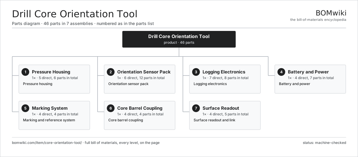
| # | Part | Qty | What it does |
|---|---|---|---|
| 1 | Pressure Housing 5 parts | 1× | Pressure housing |
| 2 | Orientation Sensor Pack 6 parts | 1× | Orientation sensor pack |
| 3 | Logging Electronics 7 parts | 1× | Logging electronics |
| 4 | Battery and Power 4 parts | 1× | Battery and power |
| 5 | Marking System 4 parts | 1× | Marking and reference system |
| 6 | Core Barrel Coupling 4 parts | 1× | Core barrel coupling |
| 7 | Surface Readout 4 parts | 1× | Surface readout and link |
3D model
No 3D model yet. Have a CAD file of this? Add a 3D model — STL renders right on this page; STEP, FreeCAD, and OpenSCAD sources are welcome too (openly licensed, like all 3D models on BOMwiki).
Build & assembly graph
expand / collapse · shared sub-assemblies converge · links to related products · est. labourTap an assembly to expand/collapse · tap a part to open it · use “Open page” for any node · drag to pan, scroll to zoom.
Bill of materials for Drill Core Orientation Tool
7 top-level lines · 41 rows shown · 46 parts total · indented to 3 levels| # | Item / sub-assembly | Part no. | Qty/assy | Ext. qty | Parts | Type |
|---|---|---|---|---|---|---|
| 1 | Pressure Housing 5 parts | core-orientation-tool-housing | 1× | 1 | 6 | assembly |
| 1.1 | Housing Barrel | core-orientation-tool-barrel | 1× | 1 | · | part |
| 1.2 | End Cap | core-orientation-tool-end-cap | 2× | 2 | · | part |
| 1.3 | O-Ring Set | oring-set | 1× | 1 | · | part |
| 1.4 | Shock Mount | core-orientation-tool-shock-mount | 1× | 1 | · | part |
| 1.5 | Fastener Set | fastener-set | 1× | 1 | · | part |
| 2 | Orientation Sensor Pack 6 parts | core-orientation-tool-sensor | 1× | 1 | 12 | assembly |
| 2.1 | MEMS Accelerometer | core-orientation-tool-accel | 3× | 3 | · | part |
| 2.2 | MEMS Gyro | core-orientation-tool-gyro | 3× | 3 | · | part |
| 2.3 | Fluxgate Magnetometer | core-orientation-tool-mag | 3× | 3 | · | part |
| 2.4 | Temperature Sensor | core-orientation-tool-temp | 1× | 1 | · | part |
| 2.5 | Bare PCB | pcb-bare | 1× | 1 | · | part |
| 2.6 | SMD Passive (R/C/L) | smd-passives | 1× | 1 | · | part |
| 3 | Logging Electronics 7 parts | core-orientation-tool-electronics | 1× | 1 | 8 | assembly |
| 3.1 | Microcontroller | mcu | 1× | 1 | · | part |
| 3.2 | Flash Memory | core-orientation-tool-memory | 1× | 1 | · | part |
| 3.3 | Real-Time Clock | core-orientation-tool-rtc | 1× | 1 | · | part |
| 3.4 | Vibration Detector | core-orientation-tool-vibration | 1× | 1 | · | part |
| 3.5 | Bare PCB | pcb-bare | 1× | 1 | · | part |
| 3.6 | SMD Passive (R/C/L) | smd-passives | 1× | 1 | · | part |
| 3.7 | Connector | connector | 2× | 2 | · | part |
| 4 | Battery and Power 4 parts | core-orientation-tool-power | 1× | 1 | 7 | assembly |
| 4.1 | Lithium Cell | core-orientation-tool-cell | 4× | 4 | · | part |
| 4.2 | Voltage Regulator | core-orientation-tool-regulator | 1× | 1 | · | part |
| 4.3 | Charge Port | core-orientation-tool-charge-port | 1× | 1 | · | part |
| 4.4 | Bare PCB | pcb-bare | 1× | 1 | · | part |
| 5 | Marking System 4 parts | core-orientation-tool-mark | 1× | 1 | 4 | assembly |
| 5.1 | Reference Scribe | core-orientation-tool-scribe | 1× | 1 | · | part |
| 5.2 | Toolface LED Ring | core-orientation-tool-led-ring | 1× | 1 | · | part |
| 5.3 | Orientation Line | core-orientation-tool-orient-line | 1× | 1 | · | part |
| 5.4 | Core Marker | core-orientation-tool-marker-pen | 1× | 1 | · | part |
| 6 | Core Barrel Coupling 4 parts | core-orientation-tool-coupling | 1× | 1 | 4 | assembly |
| 6.1 | Spearhead Adapter | core-orientation-tool-spearhead | 1× | 1 | · | part |
| 6.2 | Stop Ring | core-orientation-tool-stop-ring | 1× | 1 | · | part |
| 6.3 | Landing Ring | core-orientation-tool-landing-ring | 1× | 1 | · | part |
| 6.4 | Fastener Set | fastener-set | 1× | 1 | · | part |
| 7 | Surface Readout 4 parts | core-orientation-tool-comms | 1× | 1 | 5 | assembly |
| 7.1 | Handheld Reader | core-orientation-tool-reader | 1× | 1 | · | part |
| 7.2 | Data Link | core-orientation-tool-link | 1× | 1 | · | part |
| 7.3 | LCD Panel | lcd-panel | 1× | 1 | · | part |
| 7.4 | Connector | connector | 2× | 2 | · | part |
Related products
same domain, ranked by shared parts Drilling Jumbo
175 parts · shares 2 with this page
Drilling Jumbo
175 parts · shares 2 with this page
 Electrowinning Cell
347 parts · shares 2 with this page
Electrowinning Cell
347 parts · shares 2 with this page
 Gold Elution Column
128 parts · shares 2 with this page
Gold Elution Column
128 parts · shares 2 with this page
 Gravity Concentrating Table
184 parts · shares 2 with this page
Gravity Concentrating Table
184 parts · shares 2 with this page
 Large Hydraulic Mining Excavator
494 parts · shares 2 with this page
Longwall Shearer
302 parts · shares 2 with this page
Large Hydraulic Mining Excavator
494 parts · shares 2 with this page
Longwall Shearer
302 parts · shares 2 with this page
Sourcing: possible vendors
Prices, MOQ, and lead times are algorithmic estimates, not quotes, and not claims about these companies. Company mappings are curated by keyword; est. price band $200k–$5M. How estimates work| Vendor | HQ | Specialty | MOQ | Lead time |
|---|---|---|---|---|
| caterpillar.com ↗ | Irving, US | Construction & mining equipment | made to order | 20–36 wks |
|
🇯🇵Komatsu
komatsu.com ↗
|
Tokyo, JP | Construction & mining equipment | made to order | 20–36 wks |
|
🇸🇪Sandvik
rocktechnology.sandvik ↗
|
Stockholm, SE | Mining & rock technology | made to order | 20–36 wks |
|
🇸🇪Epiroc
epiroc.com ↗
|
Stockholm, SE | Mining & drilling equipment | made to order | 20–36 wks |
|
🇫🇮Metso
metso.com ↗
|
Helsinki, FI | Crushing & minerals processing | made to order | 20–36 wks |
1,034-word article