Vertical Shaft Impact Crusher
ProductOverview
A vertical shaft impact crusher, or VSI, breaks rock by throwing it rather than squeezing it. Feed drops into the centre of a fast-spinning rotor, the rotor flings each piece outward at high speed, and the rock breaks when it hits either a bed of other rock or a ring of fixed anvils. Because the energy comes from velocity, a VSI makes a cubical, well-shaped product from feed that is already fairly small. It sits at the end of a crushing train, after jaw and cone crushers have reduced quarry rock to roughly 50 mm or less, and turns that into manufactured sand and fine aggregate for concrete and asphalt.
The machine is built around eight subsystems on one base. The Rotor Assembly does the work, the Crushing Chamber is where the rock breaks, the Main Shaft Assembly carries the rotor, the Twin-Motor Drive turns it, the Feed System meters rock into the centre, the Lubrication Unit keeps the bearings alive, the Base Frame and Housing holds it together on isolators, and the Control and Instrumentation watches over all of it.
The rotor
The rotor is the heart of the machine. The Rotor Hub is a balanced steel casting bolted to the top of the spindle, and it carries the wear parts that take the rock. Feed lands first on the Feed Cone and then on the Distributor Plate, a plate that spreads it evenly to each of the three or four ports so the rotor stays in balance. Centrifugal force drives the rock outward along each port, where it runs over a Wear Tip of tungsten carbide held in a Tip Holder. The tip is the last metal the rock touches and the highest-wear part in the crusher, so it is built to be changed quickly. The hub faces are protected by an Upper Wear Plate and a Lower Wear Plate. Inside each port a Rock Cavity fills with feed rock and packs solid, so that passing rock runs over a bed of itself instead of over steel. Rock wearing on rock lasts far longer than rock wearing on metal, which is why the rotor can run for long periods between rebuilds.
Rock-on-rock and rock-on-anvil
A VSI breaks rock in one of two ways, set by how the Crushing Chamber is built. In rock-on-rock the chamber carries a Rock Shelf that holds a packed bed of feed rock around the rotor. Thrown rock strikes that bed, so rock breaks rock and the only wear is on the rotor itself. This mode gives the best particle shape and the lowest wear cost, and it is the usual choice for making sand. In rock-on-anvil the chamber instead carries an Anvil Ring holding several Anvil segments at the impact radius. Thrown rock hits the hard anvil face directly, which gives a higher reduction ratio and more fines but wears the anvils fast. Rebounding rock is caught by the Upper Chamber Liner and the Roof Liner, and the broken product falls through the Discharge Cone to the belt below. Operators pick the mode by the product they need and the abrasiveness of the rock.
Feed and cascade
Rock reaches the rotor through the Feed System. The Feed Hopper steadies the column off the supply belt, and the Feed Tube drops it onto the centre of the distributor. Not all of the feed has to go through the rotor. The Cascade Splitter diverts part of the feed straight down the outside of the rotor and into the chamber, where it adds to the rock bed and raises throughput at a lower reduction. The Cascade Gate sets how much feed takes that bypass path. Running more cascade lifts tonnes per hour but coarsens the product, so the gate is the main lever for trading capacity against fineness. Feed liners protect the hopper and tube where the abrasive column runs.
Main shaft and drive
The rotor sits on the Vertical Spindle, a forged vertical shaft carried in two Ball Bearing units inside the Bearing Cartridge, a cartridge that draws out as a unit for service. A Balance Cone under the rotor trims residual unbalance so the bearings see low vibration. The drive is at the bottom: the Driven Sheave takes a Drive Belt set from two Drive Motor units mounted on a Motor Base that slides to set belt tension. Each motor is a standard induction machine with a Stator Assembly and a Rotor Assembly in the Motor Frame. Twin motors split the high inertia load and let the crusher start against a heavy rotor without a single oversized machine. The belts run behind a Belt Guard.
Lubrication and control
The spindle bearings carry the whole rotor at speed, so they get a forced oil supply. The Lubrication Unit runs an Oil Pump that circulates oil from the Oil Reservoir through the Oil Cooler and the Oil Filter elements to the bearings. An Reservoir Heater warms cold oil before start so it can prime. The Control and Instrumentation interlocks everything: the PLC Controller will not start the Motor Starter until oil pressure is proven, and it trips the drive if a Vibration Sensor sees the unbalance that a lost wear tip would cause or a Bearing Temperature Sensor reads a hot bearing. Those trips protect a rotor that stores a large amount of energy when it is spinning.
Variants and use
VSI crushers are the shaping stage of an aggregate plant. Quarries run them to make manufactured sand where natural sand is scarce or restricted, and to clean up the shape of crushed stone that comes off cone crushers with too many flat and elongated pieces. Rock-on-rock builds suit hard, abrasive rock such as granite and basalt, while rock-on-anvil builds suit softer rock where the higher reduction is worth the anvil wear. The same frame is used fixed in a plant or mounted on a wheeled or tracked chassis for mobile work, and tip and liner sets are matched to the rock so that a site can tune both product shape and wear cost to its own feed.
Vertical Shaft Impact Crusher parts and their functions
8 top-level parts · 176 parts in total · full bill of materials below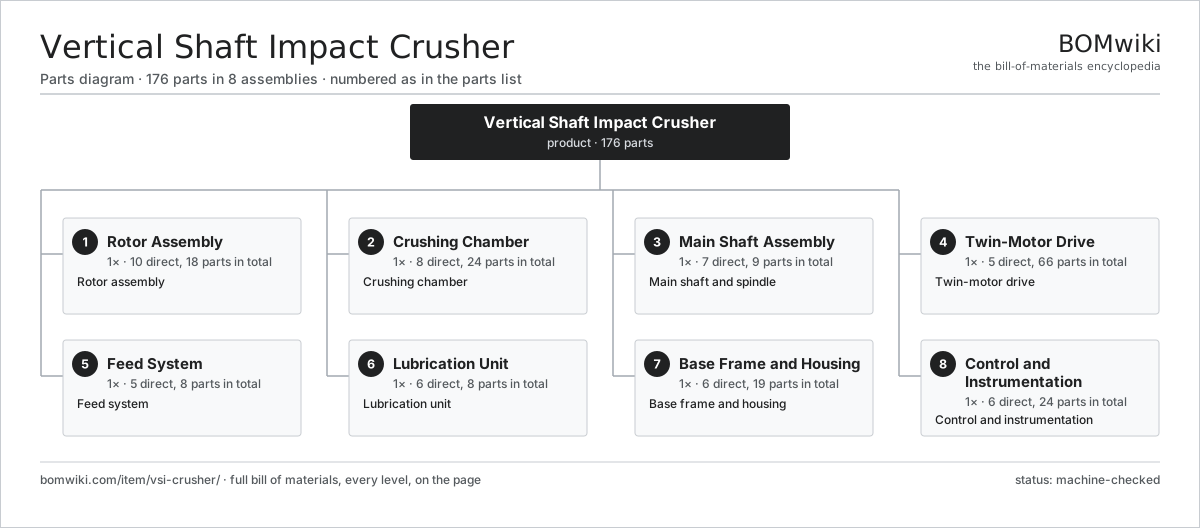
| # | Part | Qty | What it does |
|---|---|---|---|
| 1 | Rotor Assembly 10 parts | 1× | Rotor assembly |
| 2 | Crushing Chamber 8 parts | 1× | Crushing chamber |
| 3 | Main Shaft Assembly 7 parts | 1× | Main shaft and spindle |
| 4 | Twin-Motor Drive 5 parts | 1× | Twin-motor drive |
| 5 | Feed System 5 parts | 1× | Feed system |
| 6 | Lubrication Unit 6 parts | 1× | Lubrication unit |
| 7 | Base Frame and Housing 6 parts | 1× | Base frame and housing |
| 8 | Control and Instrumentation 6 parts | 1× | Control and instrumentation |
3D model
No 3D model yet. Have a CAD file of this? Add a 3D model — STL renders right on this page; STEP, FreeCAD, and OpenSCAD sources are welcome too (openly licensed, like all 3D models on BOMwiki).
Build & assembly graph
expand / collapse · shared sub-assemblies converge · links to related products · est. labourTap an assembly to expand/collapse · tap a part to open it · use “Open page” for any node · drag to pan, scroll to zoom.
Bill of materials for Vertical Shaft Impact Crusher
8 top-level lines · 73 rows shown · 176 parts total · indented to 3 levels| # | Item / sub-assembly | Part no. | Qty/assy | Ext. qty | Parts | Type |
|---|---|---|---|---|---|---|
| 1 | Rotor Assembly 10 parts | vsi-crusher-rotor | 1× | 1 | 18 | assembly |
| 1.1 | Rotor Hub | vsi-crusher-rotor-hub | 1× | 1 | · | part |
| 1.2 | Distributor Plate | vsi-crusher-distributor | 1× | 1 | · | part |
| 1.3 | Feed Cone | vsi-crusher-feed-cone | 1× | 1 | · | part |
| 1.4 | Wear Tip | vsi-crusher-wear-tip | 3× | 3 | · | part |
| 1.5 | Tip Holder | vsi-crusher-tip-holder | 3× | 3 | · | part |
| 1.6 | Upper Wear Plate | vsi-crusher-upper-wear-plate | 3× | 3 | · | part |
| 1.7 | Lower Wear Plate | vsi-crusher-lower-wear-plate | 3× | 3 | · | part |
| 1.8 | Rock Cavity | vsi-crusher-rotor-cavity | 1× | 1 | · | part |
| 1.9 | Top Wear Cap | vsi-crusher-rotor-top-cap | 1× | 1 | · | part |
| 1.10 | Fastener Set | fastener-set | 1× | 1 | · | part |
| 2 | Crushing Chamber 8 parts | vsi-crusher-chamber | 1× | 1 | 24 | assembly |
| 2.1 | Chamber Shell | vsi-crusher-chamber-shell | 1× | 1 | · | part |
| 2.2 | Rock Shelf | vsi-crusher-rock-shelf | 1× | 1 | · | part |
| 2.3 | Anvil Ring | vsi-crusher-anvil-ring | 1× | 1 | · | part |
| 2.4 | Anvil | vsi-crusher-anvil | 8× | 8 | · | part |
| 2.5 | Upper Chamber Liner | vsi-crusher-upper-chamber-liner | 6× | 6 | · | part |
| 2.6 | Roof Liner | vsi-crusher-roof-liner | 4× | 4 | · | part |
| 2.7 | Discharge Cone | vsi-crusher-discharge-cone | 1× | 1 | · | part |
| 2.8 | Inspection Door | vsi-crusher-access-door | 2× | 2 | · | part |
| 3 | Main Shaft Assembly 7 parts | vsi-crusher-shaft | 1× | 1 | 9 | assembly |
| 3.1 | Vertical Spindle | vsi-crusher-spindle | 1× | 1 | · | part |
| 3.2 | Bearing Cartridge | vsi-crusher-bearing-housing | 1× | 1 | · | part |
| 3.3 | Ball Bearing | ball-bearing | 2× | 2 | · | part |
| 3.4 | Driven Sheave | vsi-crusher-lower-sheave | 1× | 1 | · | part |
| 3.5 | Oil Seal | oil-seal | 2× | 2 | · | part |
| 3.6 | O-Ring Set | oring-set | 1× | 1 | · | part |
| 3.7 | Balance Cone | vsi-crusher-balance-cone | 1× | 1 | · | part |
| 4 | Twin-Motor Drive 5 parts | vsi-crusher-drive | 1× | 1 | 66 | assembly |
| 4.1 | Drive Motor 4 parts | vsi-crusher-motor | 2× | 2 | 25 | assembly |
| 4.1.1 | Stator Assembly 3 parts + deeper › | stator-assembly | 1× | 2 | 3 | assembly |
| 4.1.2 | Rotor Assembly 4 parts + deeper › | rotor-assembly | 1× | 2 | 19 | assembly |
| 4.1.3 | Ball Bearing | ball-bearing | 2× | 4 | · | part |
| 4.1.4 | Motor Frame | vsi-crusher-motor-frame | 1× | 2 | · | part |
| 4.2 | Motor Sheave | vsi-crusher-drive-sheave | 2× | 2 | · | part |
| 4.3 | Drive Belt | drive-belt | 12× | 12 | · | part |
| 4.4 | Motor Base | vsi-crusher-motor-base | 1× | 1 | · | part |
| 4.5 | Belt Guard | vsi-crusher-belt-guard | 1× | 1 | · | part |
| 5 | Feed System 5 parts | vsi-crusher-feed | 1× | 1 | 8 | assembly |
| 5.1 | Feed Hopper | vsi-crusher-feed-hopper | 1× | 1 | · | part |
| 5.2 | Feed Tube | vsi-crusher-feed-tube | 1× | 1 | · | part |
| 5.3 | Cascade Splitter | vsi-crusher-cascade-splitter | 1× | 1 | · | part |
| 5.4 | Cascade Gate | vsi-crusher-cascade-gate | 1× | 1 | · | part |
| 5.5 | Feed Liner | vsi-crusher-feed-liner | 4× | 4 | · | part |
| 6 | Lubrication Unit 6 parts | vsi-crusher-lube | 1× | 1 | 8 | assembly |
| 6.1 | Oil Pump | vsi-crusher-oil-pump | 1× | 1 | · | part |
| 6.2 | Oil Reservoir | vsi-crusher-oil-reservoir | 1× | 1 | · | part |
| 6.3 | Oil Cooler | vsi-crusher-oil-cooler | 1× | 1 | · | part |
| 6.4 | Oil Filter | vsi-crusher-oil-filter | 2× | 2 | · | part |
| 6.5 | Reservoir Heater 1 parts | vsi-crusher-oil-heater | 1× | 1 | 1 | assembly |
| 6.5.1 | Heating Element | heating-element | 1× | 1 | · | part |
| 6.6 | Pressure Sensor | pressure-sensor | 2× | 2 | · | part |
| 7 | Base Frame and Housing 6 parts | vsi-crusher-frame | 1× | 1 | 19 | assembly |
| 7.1 | Base Weldment | vsi-crusher-base-weldment | 1× | 1 | · | part |
| 7.2 | Isolation Mount | vsi-crusher-isolation-mount | 6× | 6 | · | part |
| 7.3 | Housing Panel | vsi-crusher-housing-panel | 1× | 1 | · | part |
| 7.4 | Lifting Lug | vsi-crusher-lifting-lug | 4× | 4 | · | part |
| 7.5 | Sheet Metal Panel | sheet-panel | 6× | 6 | · | part |
| 7.6 | Fastener Set | fastener-set | 1× | 1 | · | part |
| 8 | Control and Instrumentation 6 parts | vsi-crusher-control | 1× | 1 | 24 | assembly |
| 8.1 | PLC Controller 5 parts | vsi-crusher-plc | 1× | 1 | 5 | assembly |
| 8.1.1 | Bare PCB | pcb-bare | 1× | 1 | · | part |
| 8.1.2 | Microcontroller | mcu | 1× | 1 | · | part |
| 8.1.3 | SMD Passive (R/C/L) | smd-passives | 1× | 1 | · | part |
| 8.1.4 | LCD Panel | lcd-panel | 1× | 1 | · | part |
| 8.1.5 | Power Supply | power-supply | 1× | 1 | · | part |
| 8.2 | Motor Starter 2 parts | vsi-crusher-motor-starter | 2× | 2 | 3 | assembly |
| 8.2.1 | Relay | relay | 2× | 4 | · | part |
| 8.2.2 | Contactor | vsi-crusher-contactor | 1× | 2 | · | part |
| 8.3 | Vibration Sensor | vsi-crusher-vibration-sensor | 2× | 2 | · | part |
| 8.4 | Bearing Temperature Sensor | vsi-crusher-temp-sensor | 2× | 2 | · | part |
| 8.5 | Wire Bundle | wire-bundle | 1× | 1 | · | part |
| 8.6 | Connector | connector | 8× | 8 | · | part |
Related products
same domain, ranked by shared parts Electrowinning Cell
347 parts · shares 12 with this page
Electrowinning Cell
347 parts · shares 12 with this page
 Gold Elution Column
128 parts · shares 12 with this page
Gold Elution Column
128 parts · shares 12 with this page
 Carbon Regeneration Kiln
141 parts · shares 11 with this page
Carbon Regeneration Kiln
141 parts · shares 11 with this page
 Gravity Concentrating Table
184 parts · shares 13 with this page
Double Roll Crusher
214 parts · shares 12 with this page
Gravity Concentrating Table
184 parts · shares 13 with this page
Double Roll Crusher
214 parts · shares 12 with this page
Sourcing: possible vendors
Prices, MOQ, and lead times are algorithmic estimates, not quotes, and not claims about these companies. Company mappings are curated by keyword; est. price band $200k–$5M. How estimates work| Vendor | HQ | Specialty | MOQ | Lead time |
|---|---|---|---|---|
| caterpillar.com ↗ | Irving, US | Construction & mining equipment | made to order | 20–36 wks |
|
🇯🇵Komatsu
komatsu.com ↗
|
Tokyo, JP | Construction & mining equipment | made to order | 20–36 wks |
|
🇸🇪Sandvik
rocktechnology.sandvik ↗
|
Stockholm, SE | Mining & rock technology | made to order | 20–36 wks |
|
🇸🇪Epiroc
epiroc.com ↗
|
Stockholm, SE | Mining & drilling equipment | made to order | 20–36 wks |
|
🇫🇮Metso
metso.com ↗
|
Helsinki, FI | Crushing & minerals processing | made to order | 20–36 wks |
1,100-word article