Mobile Crushing Plant
ProductOverview
A mobile crushing plant is a crusher, a feeder, a power unit and conveyors built onto one tracked chassis so the first stage of aggregate production can happen at the quarry face instead of at a fixed plant. An excavator or wheel loader tips run-of-mine rock into the hopper, the plant crushes it to a coarse product, and a conveyor builds a stockpile or feeds the next machine. Because the plant moves on its own crawlers, it follows the dig as the face advances, which cuts the haulage that a fixed plant would need.
The eight modules sit on a common frame. The Vibrating Grizzly Feeder meters rock and scalps out fines, the Jaw Crusher does the crushing, the Diesel Power Unit drives everything, the Discharge Conveyor carries product away, the Overband Magnet pulls out tramp steel, and the Tracked Undercarriage move the plant, all coordinated by the Control System.
The jaw crusher
The heart of the plant is a single-toggle jaw crusher. Feed rock falls between a Fixed Jaw Plate bolted to the frame and a Swing Jaw that swings toward and away from it. The swing jaw hangs on the Eccentric Shaft, a forged shaft whose offset throw drives the Pitman in an elliptical motion. On the closing stroke the gap narrows and the rock is nipped and broken; on the opening stroke the broken pieces drop lower into the chamber, where they are crushed again, until they pass out of the bottom gap. That bottom gap is the closed-side setting, and it fixes the product size. The CSS Adjuster sets it hydraulically, so an operator can change product size in minutes without shims.
Both jaw faces are manganese-steel liners that work-harden under impact. They are the main wear items and are replaced when the profile is worn flat. The Toggle Plate at the back of the swing jaw is a deliberate weak link: if a digger tooth or other uncrushable lump enters, the toggle shears and saves the crusher from a shock that would crack the frame. The Flywheel Pulley is a heavy flywheel that stores energy between strokes so the engine sees a smooth load rather than a sharp pulse each time a rock breaks.
Feeding and scalping
Rock does not go straight to the jaw. The Vibrating Grizzly Feeder is a vibrating pan driven by the Feeder Exciter, an eccentric shaft with Unbalance Weight masses that throw the pan in a steady linear stroke. The pan shakes rock forward off the Feed Hopper toward the crusher mouth. Near the discharge end the pan floor is a Grizzly Bar Deck deck, a set of tapered bars spaced so that fines and quarry dirt fall through before they ever reach the jaw. Sending fines through the crusher would waste capacity and load the chamber with material that is already small enough, so the scalped fines drop into the Bypass Chute and join the product belt, or go to a separate side conveyor when the dirt has to be kept out of the saleable product.
Power and hydraulics
A Diesel Engine, usually a turbocharged in-line six diesel with SCR aftertreatment, supplies all the power. The crusher itself is normally belt-driven from the engine through a Drive Clutch that lets the engine start with no load and then bring the heavy flywheel up to speed. Every other function is hydraulic. The Hydraulic Pump Pack carries a variable Piston Pump for the main circuit and Gear Pump units for auxiliaries, drawing from the Hydraulic Reservoir. Hydraulic motors run the tracks, the feeder, the conveyors and the magnet, which means there is no mechanical driveline between modules and each can be controlled independently. A combined Oil Cooler keeps oil and charge air within limits, important because crushing runs the hydraulics hard all day.
Tracks and chassis
The Tracked Undercarriage are excavator-style crawlers. Each side has a Track Frame carrying a sprocket, an idler and a row of Track Roller units, with a sealed Track Chain running around them. A Track Drive Motor, a hydraulic motor through a planetary Gearbox Housing, drives each sprocket. The tracks are made for short repositioning moves around the pit, not for travel between sites; the plant is floated on a low loader for that. Everything bolts to the Main Frame, a box-section weldment that also carries the Walkways and Access Ladder for maintenance access.
Product handling and control
Crushed rock falls onto the Discharge Conveyor, a folding belt that runs up and away from the plant to build a stockpile. The Head Pulley Drive drives the belt, the Belt Idler rollers support it, and the Belt Scraper cleans carryback off the return run. Over the belt sits the Overband Magnet, a cross-belt magnet whose Cleaning Belt wipes captured rebar and digger teeth aside before they damage downstream screens. The whole sequence is run by the PLC Controller, which uses a Level Sensor to keep the crusher choke-fed and pressure sensors to watch the hydraulics. The operator works from a Radio Remote belt pack, tramming and stopping the plant from the ground where the view of the feed is best.
Variants and use
Jaw plants like this one are the primary crusher in a multi-stage train. The coarse product they make is fed to a mobile cone or impact crusher for secondary reduction, then to a mobile screen for sizing. Smaller versions on a single track serve recycling yards crushing concrete and asphalt, where the magnet earns its keep removing rebar. Larger versions feed quarry production lines at several hundred tonnes per hour. The tracked, self-powered format trades the lower running cost of a fixed plant for the ability to crush exactly where the rock is dug, which is decisive in contract crushing and in pits where the face moves often.
Mobile Crushing Plant parts and their functions
8 top-level parts · 143 parts in total · full bill of materials below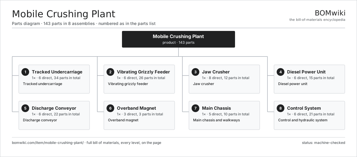
| # | Part | Qty | What it does |
|---|---|---|---|
| 1 | Tracked Undercarriage 6 parts | 1× | Tracked undercarriage |
| 2 | Vibrating Grizzly Feeder 6 parts | 1× | Vibrating grizzly feeder |
| 3 | Jaw Crusher 8 parts | 1× | Jaw crusher |
| 4 | Diesel Power Unit 6 parts | 1× | Diesel power unit |
| 5 | Discharge Conveyor 6 parts | 1× | Discharge conveyor |
| 6 | Overband Magnet 3 parts | 1× | Overband magnet |
| 7 | Main Chassis 5 parts | 1× | Main chassis and walkways |
| 8 | Control System 6 parts | 1× | Control and hydraulic system |
3D model
No 3D model yet. Have a CAD file of this? Add a 3D model — STL renders right on this page; STEP, FreeCAD, and OpenSCAD sources are welcome too (openly licensed, like all 3D models on BOMwiki).
Build & assembly graph
expand / collapse · shared sub-assemblies converge · links to related products · est. labourTap an assembly to expand/collapse · tap a part to open it · use “Open page” for any node · drag to pan, scroll to zoom.
Bill of materials for Mobile Crushing Plant
8 top-level lines · 84 rows shown · 143 parts total · indented to 3 levels| # | Item / sub-assembly | Part no. | Qty/assy | Ext. qty | Parts | Type |
|---|---|---|---|---|---|---|
| 1 | Tracked Undercarriage 6 parts | mobile-crushing-plant-tracks | 1× | 1 | 34 | assembly |
| 1.1 | Track Frame | mobile-crushing-plant-track-frame | 2× | 2 | · | part |
| 1.2 | Track Chain | mobile-crushing-plant-track-chain | 2× | 2 | · | part |
| 1.3 | Track Drive Motor 5 parts | mobile-crushing-plant-track-motor | 2× | 2 | 7 | assembly |
| 1.3.1 | Hydraulic Motor | mobile-crushing-plant-hyd-motor | 1× | 2 | · | part |
| 1.3.2 | Gearbox Housing | gearbox-housing | 1× | 2 | · | part |
| 1.3.3 | Helical Gear Pair | gear-pair | 2× | 4 | · | part |
| 1.3.4 | Ball Bearing | ball-bearing | 2× | 4 | · | part |
| 1.3.5 | Oil Seal | oil-seal | 1× | 2 | · | part |
| 1.4 | Track Roller | mobile-crushing-plant-track-roller | 12× | 12 | · | part |
| 1.5 | Front Idler | mobile-crushing-plant-idler | 2× | 2 | · | part |
| 1.6 | Drive Sprocket | mobile-crushing-plant-sprocket | 2× | 2 | · | part |
| 2 | Vibrating Grizzly Feeder 6 parts | mobile-crushing-plant-feeder | 1× | 1 | 26 | assembly |
| 2.1 | Feed Hopper | mobile-crushing-plant-hopper | 1× | 1 | · | part |
| 2.2 | Feed Pan | mobile-crushing-plant-feeder-pan | 1× | 1 | · | part |
| 2.3 | Grizzly Bar Deck | mobile-crushing-plant-grizzly-bars | 1× | 1 | · | part |
| 2.4 | Feeder Exciter 4 parts | mobile-crushing-plant-feeder-exciter | 2× | 2 | 7 | assembly |
| 2.4.1 | Eccentric Shaft | mobile-crushing-plant-eccentric-shaft | 1× | 2 | · | part |
| 2.4.2 | Ball Bearing | ball-bearing | 2× | 4 | · | part |
| 2.4.3 | Unbalance Weight | mobile-crushing-plant-counterweight | 2× | 4 | · | part |
| 2.4.4 | Oil Seal | oil-seal | 2× | 4 | · | part |
| 2.5 | Suspension Spring | mobile-crushing-plant-feeder-spring | 8× | 8 | · | part |
| 2.6 | Bypass Chute | mobile-crushing-plant-bypass-chute | 1× | 1 | · | part |
| 3 | Jaw Crusher 8 parts | mobile-crushing-plant-jaw | 1× | 1 | 12 | assembly |
| 3.1 | Crusher Frame | mobile-crushing-plant-jaw-frame | 1× | 1 | · | part |
| 3.2 | Fixed Jaw Plate | mobile-crushing-plant-fixed-jaw | 1× | 1 | · | part |
| 3.3 | Swing Jaw 4 parts | mobile-crushing-plant-swing-jaw | 1× | 1 | 5 | assembly |
| 3.3.1 | Pitman | mobile-crushing-plant-pitman | 1× | 1 | · | part |
| 3.3.2 | Swing Jaw Plate | mobile-crushing-plant-swing-plate | 1× | 1 | · | part |
| 3.3.3 | Ball Bearing | ball-bearing | 2× | 2 | · | part |
| 3.3.4 | Fastener Set | fastener-set | 1× | 1 | · | part |
| 3.4 | Eccentric Shaft | mobile-crushing-plant-jaw-eccentric | 1× | 1 | · | part |
| 3.5 | Toggle Plate | mobile-crushing-plant-toggle | 1× | 1 | · | part |
| 3.6 | Tension Rod | mobile-crushing-plant-tension-rod | 1× | 1 | · | part |
| 3.7 | Flywheel Pulley | mobile-crushing-plant-jaw-pulley | 1× | 1 | · | part |
| 3.8 | CSS Adjuster | mobile-crushing-plant-css-shim | 1× | 1 | · | part |
| 4 | Diesel Power Unit 6 parts | mobile-crushing-plant-power | 1× | 1 | 15 | assembly |
| 4.1 | Diesel Engine 4 parts | mobile-crushing-plant-engine | 1× | 1 | 4 | assembly |
| 4.1.1 | Engine Block | mobile-crushing-plant-engine-block | 1× | 1 | · | part |
| 4.1.2 | Turbocharger | mobile-crushing-plant-turbo | 1× | 1 | · | part |
| 4.1.3 | SCR Aftertreatment | mobile-crushing-plant-aftertreat | 1× | 1 | · | part |
| 4.1.4 | Radiator | mobile-crushing-plant-radiator | 1× | 1 | · | part |
| 4.2 | Drive Clutch | mobile-crushing-plant-clutch | 1× | 1 | · | part |
| 4.3 | Hydraulic Pump Pack 3 parts | mobile-crushing-plant-pump-pack | 1× | 1 | 4 | assembly |
| 4.3.1 | Piston Pump | mobile-crushing-plant-piston-pump | 1× | 1 | · | part |
| 4.3.2 | Gear Pump | mobile-crushing-plant-gear-pump | 2× | 2 | · | part |
| 4.3.3 | Hydraulic Reservoir | mobile-crushing-plant-hyd-tank | 1× | 1 | · | part |
| 4.4 | Fuel Tank | mobile-crushing-plant-fuel-tank | 1× | 1 | · | part |
| 4.5 | Oil Cooler | mobile-crushing-plant-cooler | 1× | 1 | · | part |
| 4.6 | Drive Belt | drive-belt | 4× | 4 | · | part |
| 5 | Discharge Conveyor 6 parts | mobile-crushing-plant-discharge | 1× | 1 | 22 | assembly |
| 5.1 | Conveyor Belt | mobile-crushing-plant-belt | 1× | 1 | · | part |
| 5.2 | Head Pulley Drive 3 parts | mobile-crushing-plant-head-pulley | 1× | 1 | 4 | assembly |
| 5.2.1 | Drive Drum | mobile-crushing-plant-drum | 1× | 1 | · | part |
| 5.2.2 | Hydraulic Motor | mobile-crushing-plant-hyd-motor | 1× | 1 | · | part |
| 5.2.3 | Ball Bearing | ball-bearing | 2× | 2 | · | part |
| 5.3 | Tail Pulley | mobile-crushing-plant-tail-pulley | 1× | 1 | · | part |
| 5.4 | Belt Idler | mobile-crushing-plant-belt-idler | 14× | 14 | · | part |
| 5.5 | Belt Scraper | mobile-crushing-plant-belt-scraper | 1× | 1 | · | part |
| 5.6 | Conveyor Frame | mobile-crushing-plant-belt-frame | 1× | 1 | · | part |
| 6 | Overband Magnet 3 parts | mobile-crushing-plant-magnet | 1× | 1 | 3 | assembly |
| 6.1 | Magnet Block | mobile-crushing-plant-magnet-block | 1× | 1 | · | part |
| 6.2 | Cleaning Belt | mobile-crushing-plant-magnet-belt | 1× | 1 | · | part |
| 6.3 | Hydraulic Motor | mobile-crushing-plant-hyd-motor | 1× | 1 | · | part |
| 7 | Main Chassis 5 parts | mobile-crushing-plant-chassis | 1× | 1 | 10 | assembly |
| 7.1 | Main Frame | mobile-crushing-plant-main-frame | 1× | 1 | · | part |
| 7.2 | Walkways | mobile-crushing-plant-walkway | 1× | 1 | · | part |
| 7.3 | Access Ladder | mobile-crushing-plant-ladder | 1× | 1 | · | part |
| 7.4 | Sheet Metal Panel | sheet-panel | 6× | 6 | · | part |
| 7.5 | Fastener Set | fastener-set | 1× | 1 | · | part |
| 8 | Control System 6 parts | mobile-crushing-plant-control | 1× | 1 | 21 | assembly |
| 8.1 | PLC Controller 4 parts | mobile-crushing-plant-plc | 1× | 1 | 4 | assembly |
| 8.1.1 | Bare PCB | pcb-bare | 1× | 1 | · | part |
| 8.1.2 | Microcontroller | mcu | 1× | 1 | · | part |
| 8.1.3 | SMD Passive (R/C/L) | smd-passives | 1× | 1 | · | part |
| 8.1.4 | LCD Panel | lcd-panel | 1× | 1 | · | part |
| 8.2 | Radio Remote | mobile-crushing-plant-remote | 1× | 1 | · | part |
| 8.3 | Valve Bank | mobile-crushing-plant-valve-bank | 1× | 1 | · | part |
| 8.4 | Sensor Set 3 parts | mobile-crushing-plant-sensor-set | 1× | 1 | 6 | assembly |
| 8.4.1 | Pressure Sensor | pressure-sensor | 3× | 3 | · | part |
| 8.4.2 | Level Sensor | mobile-crushing-plant-level-sensor | 1× | 1 | · | part |
| 8.4.3 | Speed Sensor | mobile-crushing-plant-speed-sensor | 2× | 2 | · | part |
| 8.5 | Wire Bundle | wire-bundle | 1× | 1 | · | part |
| 8.6 | Connector | connector | 8× | 8 | · | part |
Related products
same domain, ranked by shared parts Gravity Concentrating Table
184 parts · shares 5 with this page
Mechanized Scaling Rig
530 parts · shares 5 with this page
Gravity Concentrating Table
184 parts · shares 5 with this page
Mechanized Scaling Rig
530 parts · shares 5 with this page
 Mobile Screening Plant
205 parts · shares 5 with this page
Mobile Screening Plant
205 parts · shares 5 with this page
 In-Pit Crushing and Conveying System
8,200 parts · shares 4 with this page
In-Pit Crushing and Conveying System
8,200 parts · shares 4 with this page
 Mineral Jig Concentrator
145 parts · shares 4 with this page
Double Roll Crusher
214 parts · shares 3 with this page
Mineral Jig Concentrator
145 parts · shares 4 with this page
Double Roll Crusher
214 parts · shares 3 with this page
Sourcing: possible vendors
Prices, MOQ, and lead times are algorithmic estimates, not quotes, and not claims about these companies. Company mappings are curated by keyword; est. price band $200k–$5M. How estimates work| Vendor | HQ | Specialty | MOQ | Lead time |
|---|---|---|---|---|
| caterpillar.com ↗ | Irving, US | Construction & mining equipment | made to order | 20–36 wks |
|
🇯🇵Komatsu
komatsu.com ↗
|
Tokyo, JP | Construction & mining equipment | made to order | 20–36 wks |
|
🇸🇪Sandvik
rocktechnology.sandvik ↗
|
Stockholm, SE | Mining & rock technology | made to order | 20–36 wks |
|
🇸🇪Epiroc
epiroc.com ↗
|
Stockholm, SE | Mining & drilling equipment | made to order | 20–36 wks |
|
🇫🇮Metso
metso.com ↗
|
Helsinki, FI | Crushing & minerals processing | made to order | 20–36 wks |
1,083-word article