Double Roll Crusher
ProductOverview
A double roll crusher breaks coal and other friable material between two counter-rotating rolls turning toward each other. Feed drops onto the rolls, the surface speed and the tooth profile grip each lump, and the narrowing gap nips it until it breaks and passes through the bottom. Because the action is mostly a single nip rather than the repeated impact of a jaw or cone, the rolls make a controlled product with few fines, which is what coal preparation, sinter feed and many friable ores want. The machine is built around two Roll Shaft assemblies, one in fixed bearings and one that can float, with a Spring Relief and Gap Adjustment system to pass tramp iron, a Drive Train, a Frame and Housing, a Scraper and Cleaning System, a Lubrication System circuit and Control and Instrumentation.
The rolls
Each roll is a Roll Shaft carrying two Roll Hub castings, keyed on with a Drive Key. The crushing surface is not part of the shaft. It is a ring of bolt-on Toothed Wear Segment pieces held by Segment Bolt sets, so the segments wear out and get replaced while the expensive shaft and hubs stay in service. For coal the segments carry a sigma-tooth profile that bites into lumps and pulls them into the gap, which lets the rolls take a larger feed than smooth rolls of the same diameter. Smooth rolls are used for harder, more abrasive material where the product has to be closer to single sized. The two rolls turn at opposite hands so both surfaces move down into the gap.
Bearings and spring relief
Both rolls run in the Plummer-Block Bearing Set, heavy Spherical Roller Bearing units in split Plummer-Block Housing blocks. The split housing means a bearing can be changed without lifting the roll out. The Fixed Roll Assembly bearings bolt solid to the frame. The Floating Roll Assembly bearings sit in Sliding Bearing Block units that can move in guides. Behind the sliding blocks the Spring Relief and Gap Adjustment system carries Coil Spring stacks on Spring Tension Rod tension rods through a Spring Thrust Block. The springs hold the floating roll up to its set gap during normal crushing. If a piece of tramp iron, a wire rope end or a drill bit reaches the rolls, the force overcomes the springs, the floating roll retracts, the metal passes through, and the springs return the roll to its set position. This protects the rolls and the drive from a shock that would otherwise stall or break them.
Gap setting and reduction
The roll gap fixes the product top size. It is set with the Gap Adjusting Screw, which advances or retracts the Spring Thrust Block, and held by a Gap Shim Pack that takes up tooth wear as the segments lose profile. With a roll diameter of 600 to 1200 mm the machine accepts feed up to about 400 mm and works at a reduction ratio near 4:1, so a gap in the 15 to 100 mm range covers most coal and ore sizing. Because the nip happens once, the fines fraction stays low compared with a jaw or cone crusher at the same reduction.
Drive
The Drive Train uses one Drive Motor per roll, each an induction motor with a Stator Assembly and Rotor Assembly running in Ball Bearing units. The motor drives through a Fluid Coupling that lets it start unloaded and brings the roll up to speed smoothly, then cushions the torque shock when a hard lump enters. Drive Belt V-belts run from the motor to the Roll Drive Pulley on each roll shaft, set by a Belt Tensioner. A separate motor per roll keeps the two rolls independent, which matters when one roll floats and the gap changes under load. A Drive Guard encloses each belt drive.
Frame and cleaning
The Base Frame is a box-section weldment that carries the bearing seats and the sliding guides and reacts the crushing force into the foundation. Side Wall plates and a removable Top Hood close the chamber, with a Feed Inlet that spreads feed across the full roll face and a Discharge Opening below. Wear Liner Plate wear plates protect the chamber walls. Coal that is wet and sticky tends to pack into the teeth and close the gap, so the Scraper and Cleaning System system rides a Scraper Bar on a spring-loaded Scraper Arm against each roll to wipe the teeth clean as they turn.
Lubrication and control
The Lubrication System system meters grease from a Grease Pump through a Divider Block to each plummer block on a timed cycle, so the bearings never run dry. The Control and Instrumentation system starts each motor through a Motor Starter and runs the interlocks from a Crusher Controller. A Bearing Temperature Sensor in each bearing warns of a lubrication fault before the bearing seizes, a Roll Gap Sensor tracks how far the floating roll has retracted and so reports both tramp events and accumulated tooth wear, and a Pressure Sensor confirms the grease line is charged.
Variants and use
Toothed double roll crushers are the standard primary and secondary machine in coal preparation, breaking run-of-mine coal to a size the plant can wash and screen without making slimes. Smooth-roll versions handle harder friable ores and clinker where a tight product band is needed. Single-roll variants run one driven roll against a fixed breaker plate for sticky feeds, and four-roll machines stack two stages in one frame for a higher reduction in a single pass. The low fines and the gentle action are the reason the format holds its place against jaw and impact crushers wherever the product size matters more than the last bit of throughput.
Double Roll Crusher parts and their functions
9 top-level parts · 214 parts in total · full bill of materials below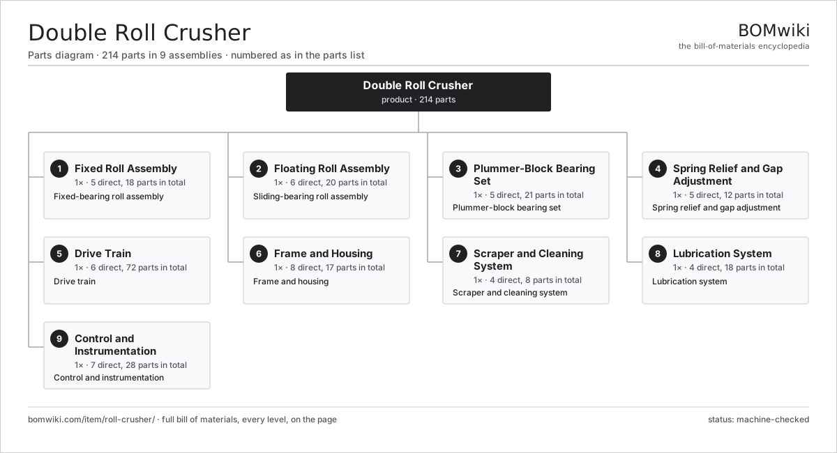
| # | Part | Qty | What it does |
|---|---|---|---|
| 1 | Fixed Roll Assembly 5 parts | 1× | Fixed-bearing roll assembly |
| 2 | Floating Roll Assembly 6 parts | 1× | Sliding-bearing roll assembly |
| 3 | Plummer-Block Bearing Set 5 parts | 1× | Plummer-block bearing set |
| 4 | Spring Relief and Gap Adjustment 5 parts | 1× | Spring relief and gap adjustment |
| 5 | Drive Train 6 parts | 1× | Drive train |
| 6 | Frame and Housing 8 parts | 1× | Frame and housing |
| 7 | Scraper and Cleaning System 4 parts | 1× | Scraper and cleaning system |
| 8 | Lubrication System 4 parts | 1× | Lubrication system |
| 9 | Control and Instrumentation 7 parts | 1× | Control and instrumentation |
3D model
No 3D model yet. Have a CAD file of this? Add a 3D model — STL renders right on this page; STEP, FreeCAD, and OpenSCAD sources are welcome too (openly licensed, like all 3D models on BOMwiki).
Build & assembly graph
expand / collapse · shared sub-assemblies converge · links to related products · est. labourTap an assembly to expand/collapse · tap a part to open it · use “Open page” for any node · drag to pan, scroll to zoom.
Bill of materials for Double Roll Crusher
9 top-level lines · 72 rows shown · 214 parts total · indented to 3 levels| # | Item / sub-assembly | Part no. | Qty/assy | Ext. qty | Parts | Type |
|---|---|---|---|---|---|---|
| 1 | Fixed Roll Assembly 5 parts | roll-crusher-fixed-roll | 1× | 1 | 18 | assembly |
| 1.1 | Roll Shaft | roll-crusher-roll-shaft | 1× | 1 | · | part |
| 1.2 | Roll Hub | roll-crusher-roll-hub | 2× | 2 | · | part |
| 1.3 | Toothed Wear Segment | roll-crusher-tooth-segment | 12× | 12 | · | part |
| 1.4 | Segment Bolt | roll-crusher-segment-bolt | 1× | 1 | · | part |
| 1.5 | Drive Key | roll-crusher-shaft-key | 2× | 2 | · | part |
| 2 | Floating Roll Assembly 6 parts | roll-crusher-floating-roll | 1× | 1 | 20 | assembly |
| 2.1 | Roll Shaft | roll-crusher-roll-shaft | 1× | 1 | · | part |
| 2.2 | Roll Hub | roll-crusher-roll-hub | 2× | 2 | · | part |
| 2.3 | Toothed Wear Segment | roll-crusher-tooth-segment | 12× | 12 | · | part |
| 2.4 | Segment Bolt | roll-crusher-segment-bolt | 1× | 1 | · | part |
| 2.5 | Drive Key | roll-crusher-shaft-key | 2× | 2 | · | part |
| 2.6 | Sliding Bearing Block | roll-crusher-slide-block | 2× | 2 | · | part |
| 3 | Plummer-Block Bearing Set 5 parts | roll-crusher-bearing-set | 1× | 1 | 21 | assembly |
| 3.1 | Plummer-Block Housing | roll-crusher-plummer-housing | 4× | 4 | · | part |
| 3.2 | Spherical Roller Bearing | roll-crusher-spherical-bearing | 4× | 4 | · | part |
| 3.3 | Oil Seal | oil-seal | 8× | 8 | · | part |
| 3.4 | Bearing End Cover | roll-crusher-end-cover | 4× | 4 | · | part |
| 3.5 | Fastener Set | fastener-set | 1× | 1 | · | part |
| 4 | Spring Relief and Gap Adjustment 5 parts | roll-crusher-spring-relief | 1× | 1 | 12 | assembly |
| 4.1 | Coil Spring | coil-spring | 4× | 4 | · | part |
| 4.2 | Spring Tension Rod | roll-crusher-spring-rod | 2× | 2 | · | part |
| 4.3 | Gap Adjusting Screw | roll-crusher-adjust-screw | 2× | 2 | · | part |
| 4.4 | Gap Shim Pack | roll-crusher-shim-pack | 2× | 2 | · | part |
| 4.5 | Spring Thrust Block | roll-crusher-thrust-block | 2× | 2 | · | part |
| 5 | Drive Train 6 parts | roll-crusher-drive | 1× | 1 | 72 | assembly |
| 5.1 | Drive Motor 5 parts | roll-crusher-motor | 2× | 2 | 26 | assembly |
| 5.1.1 | Stator Assembly 3 parts + deeper › | stator-assembly | 1× | 2 | 3 | assembly |
| 5.1.2 | Rotor Assembly 4 parts + deeper › | rotor-assembly | 1× | 2 | 19 | assembly |
| 5.1.3 | Ball Bearing | ball-bearing | 2× | 4 | · | part |
| 5.1.4 | Motor Frame | roll-crusher-motor-frame | 1× | 2 | · | part |
| 5.1.5 | Terminal Box | roll-crusher-terminal-box | 1× | 2 | · | part |
| 5.2 | Fluid Coupling | roll-crusher-fluid-coupling | 2× | 2 | · | part |
| 5.3 | Roll Drive Pulley | roll-crusher-drive-pulley | 2× | 2 | · | part |
| 5.4 | Drive Belt | drive-belt | 12× | 12 | · | part |
| 5.5 | Belt Tensioner | roll-crusher-belt-tensioner | 2× | 2 | · | part |
| 5.6 | Drive Guard | roll-crusher-guard | 2× | 2 | · | part |
| 6 | Frame and Housing 8 parts | roll-crusher-frame | 1× | 1 | 17 | assembly |
| 6.1 | Base Frame | roll-crusher-base-frame | 1× | 1 | · | part |
| 6.2 | Side Wall | roll-crusher-side-wall | 2× | 2 | · | part |
| 6.3 | Top Hood | roll-crusher-hood | 1× | 1 | · | part |
| 6.4 | Feed Inlet | roll-crusher-feed-inlet | 1× | 1 | · | part |
| 6.5 | Discharge Opening | roll-crusher-discharge | 1× | 1 | · | part |
| 6.6 | Wear Liner Plate | roll-crusher-liner-plate | 6× | 6 | · | part |
| 6.7 | Sheet Metal Panel | sheet-panel | 4× | 4 | · | part |
| 6.8 | Fastener Set | fastener-set | 1× | 1 | · | part |
| 7 | Scraper and Cleaning System 4 parts | roll-crusher-scraper | 1× | 1 | 8 | assembly |
| 7.1 | Scraper Bar | roll-crusher-scraper-bar | 2× | 2 | · | part |
| 7.2 | Scraper Arm | roll-crusher-scraper-arm | 2× | 2 | · | part |
| 7.3 | Coil Spring | coil-spring | 2× | 2 | · | part |
| 7.4 | Scraper Pivot Bush | roll-crusher-scraper-pivot | 2× | 2 | · | part |
| 8 | Lubrication System 4 parts | roll-crusher-lube | 1× | 1 | 18 | assembly |
| 8.1 | Grease Pump | roll-crusher-grease-pump | 1× | 1 | · | part |
| 8.2 | Divider Block | roll-crusher-grease-divider | 1× | 1 | · | part |
| 8.3 | Grease Feed Line | roll-crusher-grease-line | 8× | 8 | · | part |
| 8.4 | Grease Fitting | roll-crusher-grease-fitting | 8× | 8 | · | part |
| 9 | Control and Instrumentation 7 parts | roll-crusher-control | 1× | 1 | 28 | assembly |
| 9.1 | Motor Starter 3 parts | roll-crusher-starter | 2× | 2 | 4 | assembly |
| 9.1.1 | Contactor | roll-crusher-contactor | 1× | 2 | · | part |
| 9.1.2 | Relay | relay | 2× | 4 | · | part |
| 9.1.3 | Thermal Overload | roll-crusher-overload | 1× | 2 | · | part |
| 9.2 | Crusher Controller 5 parts | roll-crusher-controller | 1× | 1 | 5 | assembly |
| 9.2.1 | Bare PCB | pcb-bare | 1× | 1 | · | part |
| 9.2.2 | Microcontroller | mcu | 1× | 1 | · | part |
| 9.2.3 | SMD Passive (R/C/L) | smd-passives | 1× | 1 | · | part |
| 9.2.4 | LCD Panel | lcd-panel | 1× | 1 | · | part |
| 9.2.5 | Power Supply | power-supply | 1× | 1 | · | part |
| 9.3 | Bearing Temperature Sensor | roll-crusher-temp-sensor | 4× | 4 | · | part |
| 9.4 | Roll Gap Sensor | roll-crusher-gap-sensor | 1× | 1 | · | part |
| 9.5 | Pressure Sensor | pressure-sensor | 1× | 1 | · | part |
| 9.6 | Wire Bundle | wire-bundle | 1× | 1 | · | part |
| 9.7 | Connector | connector | 8× | 8 | · | part |
Related products
same domain, ranked by shared parts Mineral Jig Concentrator
145 parts · shares 12 with this page
Mineral Jig Concentrator
145 parts · shares 12 with this page
 Gravity Concentrating Table
184 parts · shares 12 with this page
Gravity Concentrating Table
184 parts · shares 12 with this page
 Vertical Shaft Impact Crusher
176 parts · shares 12 with this page
Raise Climber Platform
447 parts · shares 11 with this page
Vertical Shaft Impact Crusher
176 parts · shares 12 with this page
Raise Climber Platform
447 parts · shares 11 with this page
 Inclined Vibrating Screen
110 parts · shares 10 with this page
Inclined Vibrating Screen
110 parts · shares 10 with this page
Sourcing: possible vendors
Prices, MOQ, and lead times are algorithmic estimates, not quotes, and not claims about these companies. Company mappings are curated by keyword; est. price band $200k–$5M. How estimates work| Vendor | HQ | Specialty | MOQ | Lead time |
|---|---|---|---|---|
| caterpillar.com ↗ | Irving, US | Construction & mining equipment | made to order | 20–36 wks |
|
🇯🇵Komatsu
komatsu.com ↗
|
Tokyo, JP | Construction & mining equipment | made to order | 20–36 wks |
|
🇸🇪Sandvik
rocktechnology.sandvik ↗
|
Stockholm, SE | Mining & rock technology | made to order | 20–36 wks |
|
🇸🇪Epiroc
epiroc.com ↗
|
Stockholm, SE | Mining & drilling equipment | made to order | 20–36 wks |
|
🇫🇮Metso
metso.com ↗
|
Helsinki, FI | Crushing & minerals processing | made to order | 20–36 wks |
1,016-word article