Underground Mine Refrigeration Plant
ProductOverview
A mine refrigeration plant fights heat. As mines go deeper, the rock gets hotter, and below roughly two kilometers the natural temperature of the rock, the heat of machinery, and the warming of air as it is compressed by its own descent combine to make working conditions dangerous. Air that arrives at a deep face can exceed body temperature, and at high humidity the human body cannot shed its own metabolic heat. Beyond a wet-bulb temperature in the low thirties, heat stress sets in quickly. The refrigeration plant makes deep mining possible by producing chilled water and using it to cool the ventilation air to a safe condition before it reaches the crews.
The plant is a large vapor-compression refrigeration machine, the same cycle as an industrial chiller but built at mine scale and adapted to the unusual geometry of working underground. Its core is a Refrigeration Compressor, a Condenser, an Evaporator (Chiller), and an Expansion and Refrigerant Control device. Around that cycle sit the systems that connect it to the mine: a Bulk Air Cooler that transfers the cold into the air, a Pump Station that moves the water, a Heat Rejection Circuit circuit that dumps the heat, and a Plant Control System system that runs the whole thing.
The refrigeration cycle
Refrigerant boils at low pressure in the Evaporator (Chiller), absorbing heat from the service water and chilling it to a few degrees above freezing. The Refrigeration Compressor then raises the vapor to high pressure, which also raises its condensing temperature above that of the available cooling water. In the Condenser the vapor gives up its heat to condenser water and returns to liquid. The Expansion Valve drops it back to low pressure, and the cycle repeats. A Flash Economizer vessel is often added to improve efficiency by flashing off some refrigerant at an intermediate pressure. The refrigerant in mine plants is commonly ammonia, which is efficient and has no global warming potential, though it demands careful handling because it is toxic.
Compressor
The Refrigeration Compressor is the largest power consumer in the plant. Centrifugal machines use a high-speed Compressor Impeller driven through a Speed-Increasing Gearbox from a Compressor Motor, and they control capacity through Inlet Guide Vanes pre-rotation vanes that throttle the suction. Screw compressors use intermeshing rotors and a sliding valve for capacity. Either way the machine runs continuously and depends on a clean Lubrication System for its bearings, so the lubrication circuit with its Oil Cooler and Oil Filter is treated as a critical subsystem.
Heat exchangers and refrigerant control
The Condenser and Evaporator (Chiller) are shell-and-tube vessels. In the condenser, refrigerant condenses on the outside of a Condenser Tubes bundle while cooling water flows inside; in the evaporator, the arrangement absorbs heat from the water being chilled. The Expansion and Refrigerant Control group meters refrigerant and keeps it clean and dry: a Filter Drier removes moisture, a Sight Glass lets operators see the refrigerant condition, and Relief Valve devices protect the vessels against overpressure.
Delivering cold to the air
Chilled water alone does not cool people; it has to be put into the ventilation air. The Bulk Air Cooler bulk air cooler does this, either as a finned Cooling Coil Bank or as a spray chamber where chilled water from Spray Nozzle jets contacts the air directly. A Drift Eliminator strips the entrained droplets so the air leaves cool and not wet, and a Sump collects the water for return. The cooled air then travels down the intake airways to the working levels. The Pump Station circulates both the Chilled Water Pump chilled water and the Condenser Water Pump condenser water through the long pipe runs of the mine.
Heat rejection and plant location
Whatever heat the plant removes from the mine has to go somewhere, and that is the job of the Heat Rejection Circuit circuit, usually a surface Cooling Tower that rejects the heat to the atmosphere by evaporation. Where the plant is placed underground, the condenser heat may instead be rejected into the return air on its way out of the mine. Plant location is a real engineering trade. A surface plant is easy to maintain but must pump chilled water down great vertical distances, and the water gains heat and pressure as it falls. An underground plant placed near the workings is harder to build and service but recovers the energy of the descending water and delivers cold closer to where it is needed. Many deep mines use a combination, with surface plants and underground booster plants in series.
Control, power, and variants
The Plant Control System system, built around a Plant Controller reading Temperature Sensor and pressure inputs, sequences the compressors and pumps and trims capacity to match the cooling load, which swings with the production cycle and the season. The Power Distribution distribution feeds the large compressor motors through a Transformer and Switchgear, with Soft Starter units to manage the heavy starting current. Variants span a wide range: small single-compressor plants for moderately deep mines, multi-megawatt installations for the deepest gold and platinum operations, and ice-based systems that make slurry ice on surface and pump it down, using the latent heat of melting to carry far more cooling per liter than chilled water alone. The design goal is constant across all of them: keep the wet-bulb temperature at the face within safe limits so that deep ore can be mined.
Underground Mine Refrigeration Plant parts and their functions
9 top-level parts · 388 parts in total · full bill of materials below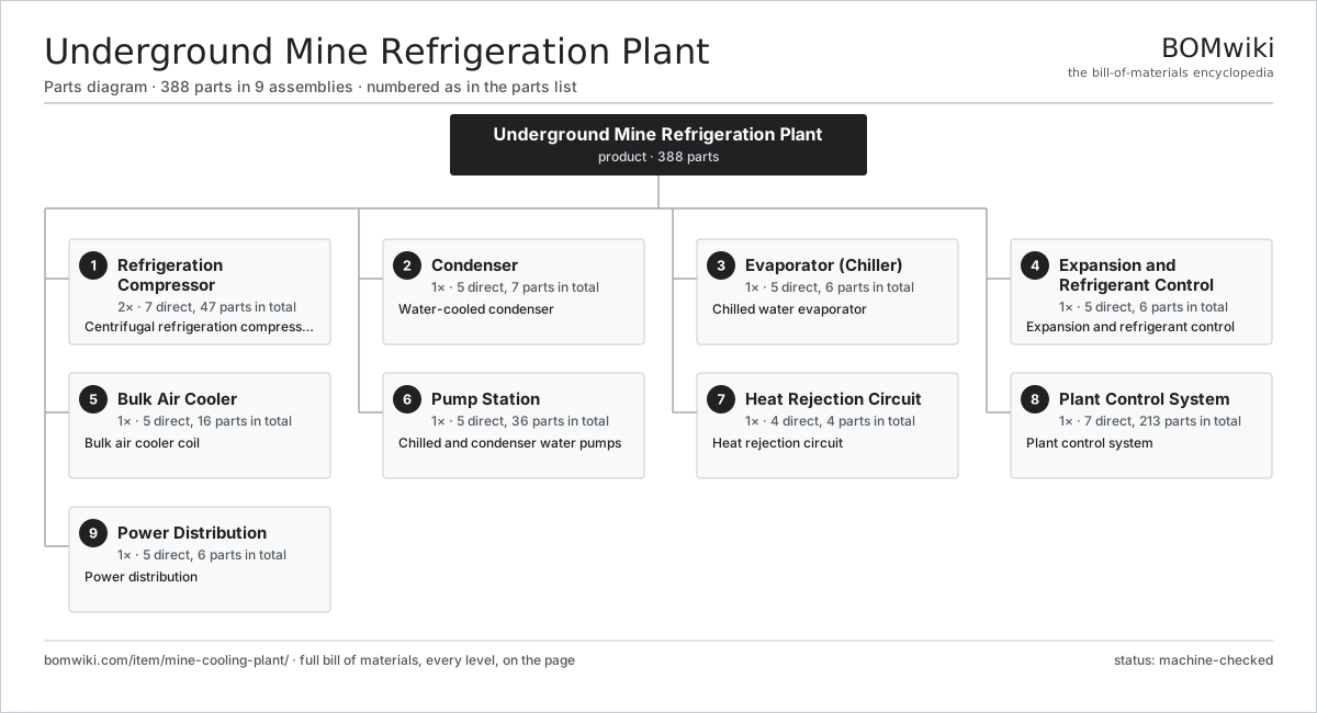
| # | Part | Qty | What it does |
|---|---|---|---|
| 1 | Refrigeration Compressor 7 parts | 2× | Centrifugal refrigeration compressor |
| 2 | Condenser 5 parts | 1× | Water-cooled condenser |
| 3 | Evaporator (Chiller) 5 parts | 1× | Chilled water evaporator |
| 4 | Expansion and Refrigerant Control 5 parts | 1× | Expansion and refrigerant control |
| 5 | Bulk Air Cooler 5 parts | 1× | Bulk air cooler coil |
| 6 | Pump Station 5 parts | 1× | Chilled and condenser water pumps |
| 7 | Heat Rejection Circuit 4 parts | 1× | Heat rejection circuit |
| 8 | Plant Control System 7 parts | 1× | Plant control system |
| 9 | Power Distribution 5 parts | 1× | Power distribution |
3D model
No 3D model yet. Have a CAD file of this? Add a 3D model — STL renders right on this page; STEP, FreeCAD, and OpenSCAD sources are welcome too (openly licensed, like all 3D models on BOMwiki).
Build & assembly graph
expand / collapse · shared sub-assemblies converge · links to related products · est. labourTap an assembly to expand/collapse · tap a part to open it · use “Open page” for any node · drag to pan, scroll to zoom.
Bill of materials for Underground Mine Refrigeration Plant
9 top-level lines · 81 rows shown · 388 parts total · indented to 3 levels| # | Item / sub-assembly | Part no. | Qty/assy | Ext. qty | Parts | Type |
|---|---|---|---|---|---|---|
| 1 | Refrigeration Compressor 7 parts | mine-cooling-plant-compressor | 2× | 2 | 47 | assembly |
| 1.1 | Compressor Impeller | mine-cooling-plant-impeller | 2× | 4 | · | part |
| 1.2 | Compressor Motor 4 parts | mine-cooling-plant-comp-motor | 1× | 2 | 25 | assembly |
| 1.2.1 | Stator Assembly 3 parts + deeper › | stator-assembly | 1× | 2 | 3 | assembly |
| 1.2.2 | Rotor Assembly 4 parts + deeper › | rotor-assembly | 1× | 2 | 19 | assembly |
| 1.2.3 | Ball Bearing | ball-bearing | 2× | 4 | · | part |
| 1.2.4 | Motor Housing | mine-cooling-plant-motor-housing | 1× | 2 | · | part |
| 1.3 | Speed-Increasing Gearbox 4 parts | mine-cooling-plant-comp-gearbox | 1× | 2 | 8 | assembly |
| 1.3.1 | Helical Gear Pair | gear-pair | 1× | 2 | · | part |
| 1.3.2 | Gearbox Housing | gearbox-housing | 1× | 2 | · | part |
| 1.3.3 | Ball Bearing | ball-bearing | 4× | 8 | · | part |
| 1.3.4 | Oil Seal | oil-seal | 2× | 4 | · | part |
| 1.4 | Inlet Guide Vanes | mine-cooling-plant-inlet-vane | 1× | 2 | · | part |
| 1.5 | Ball Bearing | ball-bearing | 4× | 8 | · | part |
| 1.6 | Oil Seal | oil-seal | 3× | 6 | · | part |
| 1.7 | Lubrication System 4 parts | mine-cooling-plant-oil-system | 1× | 2 | 4 | assembly |
| 1.7.1 | Oil Pump | mine-cooling-plant-oil-pump | 1× | 2 | · | part |
| 1.7.2 | Oil Cooler | mine-cooling-plant-oil-cooler | 1× | 2 | · | part |
| 1.7.3 | Oil Filter | mine-cooling-plant-oil-filter | 1× | 2 | · | part |
| 1.7.4 | Oil Reservoir | mine-cooling-plant-oil-tank | 1× | 2 | · | part |
| 2 | Condenser 5 parts | mine-cooling-plant-condenser | 1× | 1 | 7 | assembly |
| 2.1 | Condenser Shell | mine-cooling-plant-condenser-shell | 1× | 1 | · | part |
| 2.2 | Condenser Tubes | mine-cooling-plant-condenser-tubes | 1× | 1 | · | part |
| 2.3 | Condenser Tube Plate | mine-cooling-plant-condenser-tube-plate | 2× | 2 | · | part |
| 2.4 | Condenser Baffle | mine-cooling-plant-condenser-baffle | 1× | 1 | · | part |
| 2.5 | Water Box | mine-cooling-plant-waterbox | 2× | 2 | · | part |
| 3 | Evaporator (Chiller) 5 parts | mine-cooling-plant-evaporator | 1× | 1 | 6 | assembly |
| 3.1 | Evaporator Shell | mine-cooling-plant-evap-shell | 1× | 1 | · | part |
| 3.2 | Evaporator Tubes | mine-cooling-plant-evap-tubes | 1× | 1 | · | part |
| 3.3 | Evaporator Tube Plate | mine-cooling-plant-evap-tube-plate | 2× | 2 | · | part |
| 3.4 | Evaporator Baffle | mine-cooling-plant-evap-baffle | 1× | 1 | · | part |
| 3.5 | Refrigerant Distributor | mine-cooling-plant-evap-distributor | 1× | 1 | · | part |
| 4 | Expansion and Refrigerant Control 5 parts | mine-cooling-plant-expansion | 1× | 1 | 6 | assembly |
| 4.1 | Expansion Valve | mine-cooling-plant-expansion-valve | 1× | 1 | · | part |
| 4.2 | Flash Economizer | mine-cooling-plant-economizer | 1× | 1 | · | part |
| 4.3 | Filter Drier | mine-cooling-plant-filter-drier | 1× | 1 | · | part |
| 4.4 | Sight Glass | mine-cooling-plant-sight-glass | 1× | 1 | · | part |
| 4.5 | Relief Valve | mine-cooling-plant-relief-valve | 2× | 2 | · | part |
| 5 | Bulk Air Cooler 5 parts | mine-cooling-plant-cooling-coil | 1× | 1 | 16 | assembly |
| 5.1 | Cooling Coil Bank | mine-cooling-plant-coil-bank | 1× | 1 | · | part |
| 5.2 | Spray Nozzle | mine-cooling-plant-spray-nozzle | 12× | 12 | · | part |
| 5.3 | Drift Eliminator | mine-cooling-plant-eliminator | 1× | 1 | · | part |
| 5.4 | Sump | mine-cooling-plant-sump | 1× | 1 | · | part |
| 5.5 | Air Mover Fan | mine-cooling-plant-coil-fan | 1× | 1 | · | part |
| 6 | Pump Station 5 parts | mine-cooling-plant-pump-station | 1× | 1 | 36 | assembly |
| 6.1 | Chilled Water Pump 4 parts | mine-cooling-plant-chw-pump | 2× | 2 | 5 | assembly |
| 6.1.1 | Pump Casing | mine-cooling-plant-pump-casing | 1× | 2 | · | part |
| 6.1.2 | Pump Impeller | mine-cooling-plant-pump-impeller | 1× | 2 | · | part |
| 6.1.3 | Ball Bearing | ball-bearing | 2× | 4 | · | part |
| 6.1.4 | Oil Seal | oil-seal | 1× | 2 | · | part |
| 6.2 | Condenser Water Pump 4 parts | mine-cooling-plant-cw-pump | 2× | 2 | 5 | assembly |
| 6.2.1 | Pump Casing | mine-cooling-plant-pump-casing | 1× | 2 | · | part |
| 6.2.2 | Pump Impeller | mine-cooling-plant-pump-impeller | 1× | 2 | · | part |
| 6.2.3 | Ball Bearing | ball-bearing | 2× | 4 | · | part |
| 6.2.4 | Oil Seal | oil-seal | 1× | 2 | · | part |
| 6.3 | Pump Motor | mine-cooling-plant-pump-motor | 4× | 4 | · | part |
| 6.4 | Pump Valve | mine-cooling-plant-pump-valve | 8× | 8 | · | part |
| 6.5 | Pressure Sensor | pressure-sensor | 4× | 4 | · | part |
| 7 | Heat Rejection Circuit 4 parts | mine-cooling-plant-condenser-cooling | 1× | 1 | 4 | assembly |
| 7.1 | Cooling Tower | mine-cooling-plant-cooling-tower | 1× | 1 | · | part |
| 7.2 | Tower Fill | mine-cooling-plant-tower-fill | 1× | 1 | · | part |
| 7.3 | Tower Fan | mine-cooling-plant-tower-fan | 1× | 1 | · | part |
| 7.4 | Makeup Valve | mine-cooling-plant-makeup-valve | 1× | 1 | · | part |
| 8 | Plant Control System 7 parts | mine-cooling-plant-control | 1× | 1 | 213 | assembly |
| 8.1 | Plant Controller 4 parts | mine-cooling-plant-controller | 1× | 1 | 163 | assembly |
| 8.1.1 | Bare PCB | pcb-bare | 1× | 1 | · | part |
| 8.1.2 | Microcontroller | mcu | 2× | 2 | · | part |
| 8.1.3 | SMD Passive (R/C/L) | smd-passives | 150× | 150 | · | part |
| 8.1.4 | Connector | connector | 10× | 10 | · | part |
| 8.2 | LCD Panel | lcd-panel | 1× | 1 | · | part |
| 8.3 | Pressure Sensor | pressure-sensor | 4× | 4 | · | part |
| 8.4 | Temperature Sensor | mine-cooling-plant-temp-sensor | 8× | 8 | · | part |
| 8.5 | Wire Bundle | wire-bundle | 1× | 1 | · | part |
| 8.6 | Connector | connector | 24× | 24 | · | part |
| 8.7 | Relay | relay | 12× | 12 | · | part |
| 9 | Power Distribution 5 parts | mine-cooling-plant-power | 1× | 1 | 6 | assembly |
| 9.1 | Transformer | mine-cooling-plant-transformer | 1× | 1 | · | part |
| 9.2 | Switchgear | mine-cooling-plant-switchgear | 1× | 1 | · | part |
| 9.3 | Soft Starter | mine-cooling-plant-soft-starter | 2× | 2 | · | part |
| 9.4 | Power Supply | power-supply | 1× | 1 | · | part |
| 9.5 | Wire Bundle | wire-bundle | 1× | 1 | · | part |
Related products
same domain, ranked by shared parts Carbon Regeneration Kiln
141 parts · shares 12 with this page
Carbon Regeneration Kiln
141 parts · shares 12 with this page
 Gravity Concentrating Table
184 parts · shares 12 with this page
Mechanized Scaling Rig
530 parts · shares 12 with this page
Gravity Concentrating Table
184 parts · shares 12 with this page
Mechanized Scaling Rig
530 parts · shares 12 with this page
 Mineral Jig Concentrator
145 parts · shares 12 with this page
Mineral Jig Concentrator
145 parts · shares 12 with this page
 Flotation Column
250 parts · shares 11 with this page
Flotation Column
250 parts · shares 11 with this page
 Mining Thickener Rake Mechanism
231 parts · shares 11 with this page
Mining Thickener Rake Mechanism
231 parts · shares 11 with this page
Sourcing: possible vendors
Prices, MOQ, and lead times are algorithmic estimates, not quotes, and not claims about these companies. Company mappings are curated by keyword; est. price band $200k–$5M. How estimates work| Vendor | HQ | Specialty | MOQ | Lead time |
|---|---|---|---|---|
| caterpillar.com ↗ | Irving, US | Construction & mining equipment | made to order | 20–36 wks |
|
🇯🇵Komatsu
komatsu.com ↗
|
Tokyo, JP | Construction & mining equipment | made to order | 20–36 wks |
|
🇸🇪Sandvik
rocktechnology.sandvik ↗
|
Stockholm, SE | Mining & rock technology | made to order | 20–36 wks |
|
🇸🇪Epiroc
epiroc.com ↗
|
Stockholm, SE | Mining & drilling equipment | made to order | 20–36 wks |
|
🇫🇮Metso
metso.com ↗
|
Helsinki, FI | Crushing & minerals processing | made to order | 20–36 wks |
1,019-word article