Mining Thickener Rake Mechanism
ProductOverview
A thickener rake mechanism is the slow turning machine at the centre of a gravity thickener, the large circular tank that mineral plants use to settle fine solids out of a dilute slurry and recover clear water. The rake does two jobs at once: it gently herds the settled solids spirally inward to the central discharge cone, and by compressing the settling bed it helps water escape upward, raising the density of the underflow that leaves the bottom. It turns at a small fraction of one revolution per minute, but it must do so with enough torque to plough through a heavy mud bed without stalling.
Thickeners sit between flotation or leaching and the next stage in a plant, dewatering tailings or concentrate and clarifying process water for reuse. The mechanism is what makes a static settling tank into a continuous unit operation: without the rake, settled solids would pile up unevenly and never reach the discharge point. The same design, scaled, serves tanks from ten metres across in small plants to well over a hundred metres in large copper and alumina operations.
Drivehead
The Drivehead sits on the bridge at the tank centre and turns the whole rake. Its core is a large Slewing Bearing, an internally geared slewing ring that carries the rake weight on rolling elements and provides the gear teeth for the drive. Several Drive Motor units, each a geared electric drive, turn Drive Pinion gears that mesh with the ring, sharing the load. A Torque Sensor continuously reads how hard the rake is working, the single most important signal for protecting the mechanism. Multiple small drives instead of one large one give redundancy and let the plant keep raking on a reduced motor if one fails.
Rake arms and center shaft
Torque passes from the drivehead down the Center Shaft, a heavy vertical shaft or cage ending in a hub, to the Rake Arm Assembly. Two long Rake Arm members reach out across the tank floor, each carrying a row of angled Rake Blade plates. The blades are set at a pitch so that, as the rake turns, they push settled solids a little inward on every pass, the net effect being a slow spiral migration of mud toward the centre. The blade bottoms wear against grit, so they carry replaceable Blade Wear Shoe wear shoes, and Arm Tie Rod bracing keeps the long arms from sagging under load.
Lift system
When the slurry feed gets heavy or solids consolidate faster than they are withdrawn, the mud bed thickens and rake torque climbs. The Rake Lift System is the protection against that. On a torque signal, a Lift Motor turns a Lift Screw that raises the entire drivehead and rake clear of the heaviest mud, dropping the torque back to a safe level. As conditions recover the rake lowers again. Without a lift, a sudden bed build-up could stall the drive and bend or break the arms, so on large units the lift is automatic and staged against rising torque.
Feedwell and clarification
Incoming slurry does not just dump into the tank; it enters through the Feedwell, a central cylinder hung from the bridge. A Deaeration Box draws clarified liquor in to self-dilute the feed and release entrained air, while a Flocculant Ring injects flocculant that binds fine particles into fast-settling aggregates. Good feedwell design is what lets a modern thickener handle high rates in a smaller tank. Above the settling zone, clarified water rises and spills over the Overflow Launder, where a Overflow Weir sets the level and a peripheral trough collects recovered process water.
Underflow and control
Thickened solids collect in the Underflow System, a steep central Discharge Cone from which a Underflow Pump withdraws dense slurry. A Density Gauge and Pinch Valve let the plant hold the underflow at a target solids density, the headline product specification of the thickener. Access for all of this comes over the Access Bridge, a trussed walkway spanning the tank. The whole machine is coordinated by the Control Panel, a PLC that watches rake torque, drives the lift, trims flocculant dosing and underflow pumping, and holds the balance between a clear overflow and a dense, pumpable underflow.
Configurations and materials
The mechanism described here is a centre-drive type, where the Drivehead sits on a fixed bridge at the tank centre and is the most common arrangement on tanks up to about forty metres across. Larger tanks often use a traction drive instead, where the rake hangs from a centre column and is pulled around by a drive carriage running on a rail at the tank rim, which avoids putting the full torque through a single central bearing. A third style, the bridge-supported drive, carries the whole mechanism on a full-span bridge for tanks that cannot have a centre column. Whatever the layout, the parts that touch slurry are built for abrasion and corrosion: the Rake Arm and blades are carbon steel with replaceable Blade Wear Shoe wear shoes, and in aggressive process water the tank and rake may be epoxy coated or rubber lined. The size of the Slewing Bearing and the rating of the Drive Motor set are chosen for the worst-case bed the duty can produce, not the average one, because a thickener that cannot rake its own bed is a thickener that has stopped working. Conventional clarifier-thickeners run thin beds for clear overflow, high-rate units run deeper beds for denser underflow, and paste thickeners push consolidation all the way to a non-settling paste, each demanding more torque than the last.
Mining Thickener Rake Mechanism parts and their functions
9 top-level parts · 231 parts in total · full bill of materials below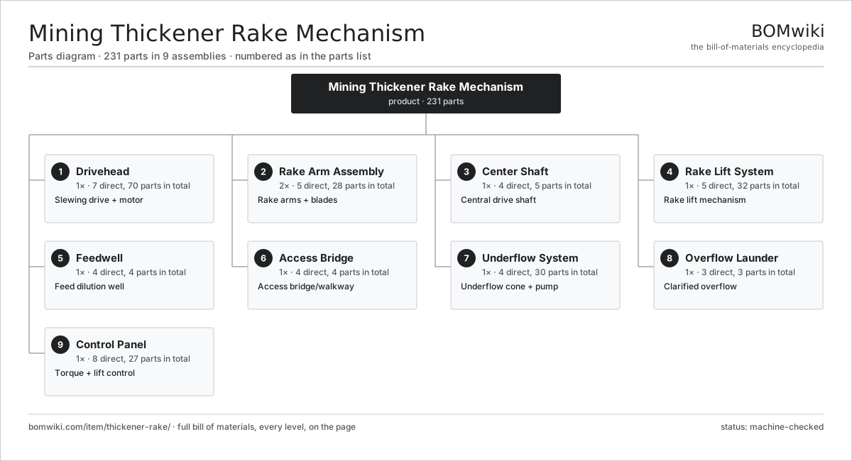
| # | Part | Qty | What it does |
|---|---|---|---|
| 1 | Drivehead 7 parts | 1× | Slewing drive + motor |
| 2 | Rake Arm Assembly 5 parts | 2× | Rake arms + blades |
| 3 | Center Shaft 4 parts | 1× | Central drive shaft |
| 4 | Rake Lift System 5 parts | 1× | Rake lift mechanism |
| 5 | Feedwell 4 parts | 1× | Feed dilution well |
| 6 | Access Bridge 4 parts | 1× | Access bridge/walkway |
| 7 | Underflow System 4 parts | 1× | Underflow cone + pump |
| 8 | Overflow Launder 3 parts | 1× | Clarified overflow |
| 9 | Control Panel 8 parts | 1× | Torque + lift control |
3D model
No 3D model yet. Have a CAD file of this? Add a 3D model — STL renders right on this page; STEP, FreeCAD, and OpenSCAD sources are welcome too (openly licensed, like all 3D models on BOMwiki).
Build & assembly graph
expand / collapse · shared sub-assemblies converge · links to related products · est. labourTap an assembly to expand/collapse · tap a part to open it · use “Open page” for any node · drag to pan, scroll to zoom.
Bill of materials for Mining Thickener Rake Mechanism
9 top-level lines · 69 rows shown · 231 parts total · indented to 3 levels| # | Item / sub-assembly | Part no. | Qty/assy | Ext. qty | Parts | Type |
|---|---|---|---|---|---|---|
| 1 | Drivehead 7 parts | thickener-rake-drivehead | 1× | 1 | 70 | assembly |
| 1.1 | Slewing Bearing | thickener-rake-slew-bearing | 1× | 1 | · | part |
| 1.2 | Drive Motor 6 parts | thickener-rake-drive-motor | 2× | 2 | 30 | assembly |
| 1.2.1 | Stator Assembly 3 parts + deeper › | stator-assembly | 1× | 2 | 3 | assembly |
| 1.2.2 | Rotor Assembly 4 parts + deeper › | rotor-assembly | 1× | 2 | 19 | assembly |
| 1.2.3 | Gearbox Housing | gearbox-housing | 1× | 2 | · | part |
| 1.2.4 | Helical Gear Pair | gear-pair | 2× | 4 | · | part |
| 1.2.5 | Ball Bearing | ball-bearing | 3× | 6 | · | part |
| 1.2.6 | Oil Seal | oil-seal | 2× | 4 | · | part |
| 1.3 | Drive Pinion | thickener-rake-drive-pinion | 2× | 2 | · | part |
| 1.4 | Gearbox Housing | gearbox-housing | 1× | 1 | · | part |
| 1.5 | Torque Sensor | thickener-rake-torque-sensor | 1× | 1 | · | part |
| 1.6 | Oil Seal | oil-seal | 4× | 4 | · | part |
| 1.7 | Fastener Set | fastener-set | 1× | 1 | · | part |
| 2 | Rake Arm Assembly 5 parts | thickener-rake-arm-assembly | 2× | 2 | 28 | assembly |
| 2.1 | Rake Arm | thickener-rake-arm | 1× | 2 | · | part |
| 2.2 | Rake Blade | thickener-rake-blade | 12× | 24 | · | part |
| 2.3 | Blade Wear Shoe | thickener-rake-blade-shoe | 12× | 24 | · | part |
| 2.4 | Arm Tie Rod | thickener-rake-tie-rod | 2× | 4 | · | part |
| 2.5 | Fastener Set | fastener-set | 1× | 2 | · | part |
| 3 | Center Shaft 4 parts | thickener-rake-center-shaft | 1× | 1 | 5 | assembly |
| 3.1 | Center Shaft | thickener-rake-shaft | 1× | 1 | · | part |
| 3.2 | Arm Hub | thickener-rake-arm-hub | 1× | 1 | · | part |
| 3.3 | Ball Bearing | ball-bearing | 2× | 2 | · | part |
| 3.4 | Fastener Set | fastener-set | 1× | 1 | · | part |
| 4 | Rake Lift System 5 parts | thickener-rake-lift-system | 1× | 1 | 32 | assembly |
| 4.1 | Lift Screw | thickener-rake-lift-screw | 1× | 1 | · | part |
| 4.2 | Lift Motor 5 parts | thickener-rake-lift-motor | 1× | 1 | 26 | assembly |
| 4.2.1 | Stator Assembly 3 parts + deeper › | stator-assembly | 1× | 1 | 3 | assembly |
| 4.2.2 | Rotor Assembly 4 parts + deeper › | rotor-assembly | 1× | 1 | 19 | assembly |
| 4.2.3 | Gearbox Housing | gearbox-housing | 1× | 1 | · | part |
| 4.2.4 | Helical Gear Pair | gear-pair | 1× | 1 | · | part |
| 4.2.5 | Ball Bearing | ball-bearing | 2× | 2 | · | part |
| 4.3 | Lift Nut | thickener-rake-lift-nut | 1× | 1 | · | part |
| 4.4 | Lift Limit Switch | thickener-rake-limit-switch | 2× | 2 | · | part |
| 4.5 | Ball Bearing | ball-bearing | 2× | 2 | · | part |
| 5 | Feedwell 4 parts | thickener-rake-feedwell | 1× | 1 | 4 | assembly |
| 5.1 | Feedwell Shell | thickener-rake-feedwell-shell | 1× | 1 | · | part |
| 5.2 | Deaeration Box | thickener-rake-deaeration-box | 1× | 1 | · | part |
| 5.3 | Flocculant Ring | thickener-rake-flocculant-ring | 1× | 1 | · | part |
| 5.4 | Feedwell Shelf | thickener-rake-feedwell-shelf | 1× | 1 | · | part |
| 6 | Access Bridge 4 parts | thickener-rake-bridge | 1× | 1 | 4 | assembly |
| 6.1 | Bridge Truss | thickener-rake-bridge-truss | 1× | 1 | · | part |
| 6.2 | Walkway Grating | thickener-rake-walkway | 1× | 1 | · | part |
| 6.3 | Handrail | thickener-rake-handrail | 1× | 1 | · | part |
| 6.4 | Fastener Set | fastener-set | 1× | 1 | · | part |
| 7 | Underflow System 4 parts | thickener-rake-underflow-system | 1× | 1 | 30 | assembly |
| 7.1 | Discharge Cone | thickener-rake-discharge-cone | 1× | 1 | · | part |
| 7.2 | Underflow Pump 5 parts | thickener-rake-underflow-pump | 1× | 1 | 27 | assembly |
| 7.2.1 | Stator Assembly 3 parts + deeper › | stator-assembly | 1× | 1 | 3 | assembly |
| 7.2.2 | Rotor Assembly 4 parts + deeper › | rotor-assembly | 1× | 1 | 19 | assembly |
| 7.2.3 | Gearbox Housing | gearbox-housing | 1× | 1 | · | part |
| 7.2.4 | Ball Bearing | ball-bearing | 2× | 2 | · | part |
| 7.2.5 | Oil Seal | oil-seal | 2× | 2 | · | part |
| 7.3 | Density Gauge | thickener-rake-density-gauge | 1× | 1 | · | part |
| 7.4 | Pinch Valve | thickener-rake-pinch-valve | 1× | 1 | · | part |
| 8 | Overflow Launder 3 parts | thickener-rake-overflow-launder | 1× | 1 | 3 | assembly |
| 8.1 | Overflow Weir | thickener-rake-weir | 1× | 1 | · | part |
| 8.2 | Launder Trough | thickener-rake-launder-trough | 1× | 1 | · | part |
| 8.3 | Overflow Pipe | thickener-rake-overflow-pipe | 1× | 1 | · | part |
| 9 | Control Panel 8 parts | thickener-rake-control-panel | 1× | 1 | 27 | assembly |
| 9.1 | Bare PCB | pcb-bare | 1× | 1 | · | part |
| 9.2 | Microcontroller | mcu | 1× | 1 | · | part |
| 9.3 | Relay | relay | 8× | 8 | · | part |
| 9.4 | Torque Sensor | thickener-rake-torque-sensor | 1× | 1 | · | part |
| 9.5 | Pressure Sensor | pressure-sensor | 2× | 2 | · | part |
| 9.6 | Wire Bundle | wire-bundle | 1× | 1 | · | part |
| 9.7 | Connector | connector | 12× | 12 | · | part |
| 9.8 | Power Supply | power-supply | 1× | 1 | · | part |
Related products
same domain, ranked by shared parts Carbon Regeneration Kiln
141 parts · shares 11 with this page
Carbon Regeneration Kiln
141 parts · shares 11 with this page
 Flotation Column
250 parts · shares 11 with this page
Flotation Column
250 parts · shares 11 with this page
 Gravity Concentrating Table
184 parts · shares 11 with this page
Mechanized Scaling Rig
530 parts · shares 11 with this page
Gravity Concentrating Table
184 parts · shares 11 with this page
Mechanized Scaling Rig
530 parts · shares 11 with this page
 Mineral Jig Concentrator
145 parts · shares 11 with this page
Paste Backfill Plant
474 parts · shares 11 with this page
Mineral Jig Concentrator
145 parts · shares 11 with this page
Paste Backfill Plant
474 parts · shares 11 with this page
Sourcing: possible vendors
Prices, MOQ, and lead times are algorithmic estimates, not quotes, and not claims about these companies. Company mappings are curated by keyword; est. price band $200k–$5M. How estimates work| Vendor | HQ | Specialty | MOQ | Lead time |
|---|---|---|---|---|
| caterpillar.com ↗ | Irving, US | Construction & mining equipment | made to order | 20–36 wks |
|
🇯🇵Komatsu
komatsu.com ↗
|
Tokyo, JP | Construction & mining equipment | made to order | 20–36 wks |
|
🇸🇪Sandvik
rocktechnology.sandvik ↗
|
Stockholm, SE | Mining & rock technology | made to order | 20–36 wks |
|
🇸🇪Epiroc
epiroc.com ↗
|
Stockholm, SE | Mining & drilling equipment | made to order | 20–36 wks |
|
🇫🇮Metso
metso.com ↗
|
Helsinki, FI | Crushing & minerals processing | made to order | 20–36 wks |
990-word article