Heap Leach Irrigation System
ProductOverview
A heap leach irrigation system applies leach solution to a pile of crushed ore so that valuable metal dissolves and drains out the bottom for recovery. The ore is stacked on a lined pad in a heap that can be a few metres high in a small gold operation or over a hundred metres in a large copper dump. Barren solution, a dilute cyanide solution for gold or dilute sulfuric acid for copper, is sprinkled or dripped evenly across the top. As it percolates down it dissolves the target metal and emerges at the base as pregnant solution. The system covers everything between the barren tank and the heap surface, plus the drains that gather the loaded solution back up: the pumps, the buried mains, the drip and sprinkler grids on the heap, the filters that keep emitters open, the reagent dosing, and the lined collection.
Even, gentle application is the whole point. Channeling, where solution finds fast paths and leaves dead zones, wastes reagent and leaves metal behind. The grid is designed to wet the heap surface uniformly at a controlled rate, then rest and rinse each cell on a schedule so the solution has time to react and the heap does not flood or slump.
Pump station
The Pump Station pressurises the network. A pair of Booster Pump units, each with an Pump Impeller in a corrosion-resistant Pump Casing and a Mechanical Seal, are driven by a Servo Motor on Ball Bearing supports with an Oil Seal at the shaft. A Variable-Frequency Drive trims pump speed to hold pressure as zone valves switch, and a Surge Tank damps the pressure swings when a cell turns on or off. Holding steady pressure matters because pressure-compensating emitters only work within a band, and large heads on a tall heap need careful pressure zoning.
Mainline and zone control
Solution leaves the station through the Mainline Piping. A buried HDPE Main carries it across the pad, polyethylene chosen because it shrugs off the corrosive chemistry and the UV exposure of years on an open heap. At each leach cell a Cell Header splits the flow into laterals, and a Zone Valve turns leach to that cell on or off so cells cycle through leach, rest and rinse on schedule. An Air Release Valve vents trapped air that would otherwise upset flow, and the network is joined with the Fitting Set of tees, saddles and clamps.
Drip and sprinkler grids
Two application methods cover different climates. The Drip Network runs Dripline laterals across the surface, each fitted with Drip Emitter units that deliver a fixed low flow regardless of slope or pressure, joined by Lateral Connector barbs and flushed by an End Flush Valve valve. Drip wets the heap with very low evaporation, which keeps cyanide losses down and reduces the visible solution plume. Where heaps run cold or freeze, the Sprinkler Network uses Wobbler Sprinkler sprinklers on Sprinkler Riser stands fed by Sprinkler Lateral pipes, each set by a Flow Regulator, because moving water resists freezing and large droplets do not block the way fine drip emitters do.
Filtration and dosing
Drip emitters have tiny passages, so the Filtration Skid skid protects them. A Coarse Strainer catches trash, then a pair of Disc Filter units strip fines to about 130 micron and clean themselves through a Backwash Valve when a Pressure Sensor detects the discs loading up. Solution chemistry is held by the Reagent Dosing Skid skid, where a Lixiviant Pump tops up lixiviant strength, a pH Modifier Pump holds pH against the pH Sensor reading, and a Reagent Day Tank feeds both. For gold the pH is kept high so cyanide stays as the active species rather than escaping as gas.
Collection, control and operation
What drains out the bottom is the point of the whole exercise. The Solution Collection system rests the heap on a welded Pad Liner, gathers solution through a Collection Drain grid in the gravel base, and routes it to a lined Pregnant Solution Pond watched by a Level Sensor pair. The Control Panel panel runs the schedule: its PLC Controller cycles zones through a Relay bank, holds application rate against the Flow Meter readings, runs the dosing loop, and tracks the solution balance, all driven from an LCD Panel and fed by a Power Supply. A leach cycle on a single lift of ore runs weeks to months; when recovery from a lift stalls, that cell is rinsed and rested while fresh ore is stacked on top, and the same barren solution, once its gold is recovered downstream, is dosed back to strength and pumped up again.
Heap Leach Irrigation System parts and their functions
8 top-level parts · 121 parts in total · full bill of materials below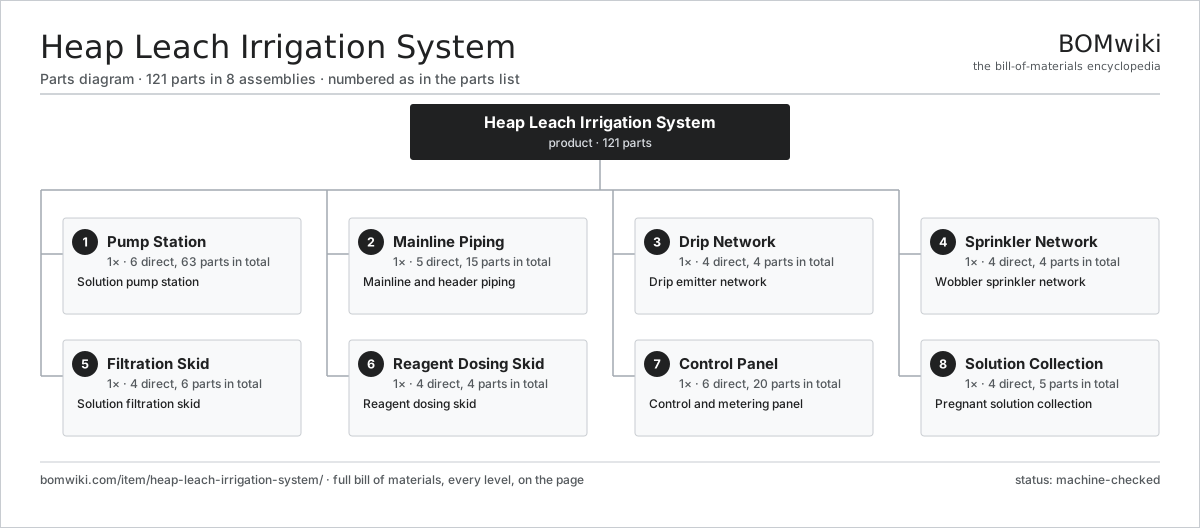
| # | Part | Qty | What it does |
|---|---|---|---|
| 1 | Pump Station 6 parts | 1× | Solution pump station |
| 2 | Mainline Piping 5 parts | 1× | Mainline and header piping |
| 3 | Drip Network 4 parts | 1× | Drip emitter network |
| 4 | Sprinkler Network 4 parts | 1× | Wobbler sprinkler network |
| 5 | Filtration Skid 4 parts | 1× | Solution filtration skid |
| 6 | Reagent Dosing Skid 4 parts | 1× | Reagent dosing skid |
| 7 | Control Panel 6 parts | 1× | Control and metering panel |
| 8 | Solution Collection 4 parts | 1× | Pregnant solution collection |
3D model
No 3D model yet. Have a CAD file of this? Add a 3D model — STL renders right on this page; STEP, FreeCAD, and OpenSCAD sources are welcome too (openly licensed, like all 3D models on BOMwiki).
Build & assembly graph
expand / collapse · shared sub-assemblies converge · links to related products · est. labourTap an assembly to expand/collapse · tap a part to open it · use “Open page” for any node · drag to pan, scroll to zoom.
Bill of materials for Heap Leach Irrigation System
8 top-level lines · 56 rows shown · 121 parts total · indented to 3 levels| # | Item / sub-assembly | Part no. | Qty/assy | Ext. qty | Parts | Type |
|---|---|---|---|---|---|---|
| 1 | Pump Station 6 parts | heap-leach-irrigation-system-pump-station | 1× | 1 | 63 | assembly |
| 1.1 | Booster Pump 3 parts | heap-leach-irrigation-system-booster-pump | 2× | 2 | 3 | assembly |
| 1.1.1 | Pump Impeller | heap-leach-irrigation-system-pump-impeller | 1× | 2 | · | part |
| 1.1.2 | Pump Casing | heap-leach-irrigation-system-pump-casing | 1× | 2 | · | part |
| 1.1.3 | Mechanical Seal | heap-leach-irrigation-system-pump-seal | 1× | 2 | · | part |
| 1.2 | Servo Motor 4 parts | servo-motor | 2× | 2 | 24 | assembly |
| 1.2.1 | Stator Assembly 3 parts + deeper › | stator-assembly | 1× | 2 | 3 | assembly |
| 1.2.2 | Rotor Assembly 4 parts + deeper › | rotor-assembly | 1× | 2 | 19 | assembly |
| 1.2.3 | Encoder | encoder | 1× | 2 | · | part |
| 1.2.4 | Motor Housing | motor-housing | 1× | 2 | · | part |
| 1.3 | Variable-Frequency Drive | heap-leach-irrigation-system-vfd | 2× | 2 | · | part |
| 1.4 | Surge Tank | heap-leach-irrigation-system-surge-tank | 1× | 1 | · | part |
| 1.5 | Ball Bearing | ball-bearing | 4× | 4 | · | part |
| 1.6 | Oil Seal | oil-seal | 2× | 2 | · | part |
| 2 | Mainline Piping 5 parts | heap-leach-irrigation-system-mainline | 1× | 1 | 15 | assembly |
| 2.1 | HDPE Main | heap-leach-irrigation-system-hdpe-main | 1× | 1 | · | part |
| 2.2 | Cell Header | heap-leach-irrigation-system-header | 1× | 1 | · | part |
| 2.3 | Zone Valve | heap-leach-irrigation-system-zone-valve | 8× | 8 | · | part |
| 2.4 | Air Release Valve | heap-leach-irrigation-system-air-valve | 4× | 4 | · | part |
| 2.5 | Fitting Set | heap-leach-irrigation-system-fitting-set | 1× | 1 | · | part |
| 3 | Drip Network 4 parts | heap-leach-irrigation-system-drip-network | 1× | 1 | 4 | assembly |
| 3.1 | Dripline | heap-leach-irrigation-system-dripline | 1× | 1 | · | part |
| 3.2 | Drip Emitter | heap-leach-irrigation-system-emitter | 1× | 1 | · | part |
| 3.3 | Lateral Connector | heap-leach-irrigation-system-lateral-connector | 1× | 1 | · | part |
| 3.4 | End Flush Valve | heap-leach-irrigation-system-end-flush | 1× | 1 | · | part |
| 4 | Sprinkler Network 4 parts | heap-leach-irrigation-system-sprinkler-network | 1× | 1 | 4 | assembly |
| 4.1 | Wobbler Sprinkler | heap-leach-irrigation-system-wobbler | 1× | 1 | · | part |
| 4.2 | Sprinkler Riser | heap-leach-irrigation-system-riser | 1× | 1 | · | part |
| 4.3 | Sprinkler Lateral | heap-leach-irrigation-system-sprinkler-lateral | 1× | 1 | · | part |
| 4.4 | Flow Regulator | heap-leach-irrigation-system-flow-regulator | 1× | 1 | · | part |
| 5 | Filtration Skid 4 parts | heap-leach-irrigation-system-filtration | 1× | 1 | 6 | assembly |
| 5.1 | Disc Filter | heap-leach-irrigation-system-disc-filter | 2× | 2 | · | part |
| 5.2 | Backwash Valve | heap-leach-irrigation-system-backwash-valve | 1× | 1 | · | part |
| 5.3 | Coarse Strainer | heap-leach-irrigation-system-strainer | 1× | 1 | · | part |
| 5.4 | Pressure Sensor | pressure-sensor | 2× | 2 | · | part |
| 6 | Reagent Dosing Skid 4 parts | heap-leach-irrigation-system-dosing | 1× | 1 | 4 | assembly |
| 6.1 | Lixiviant Pump | heap-leach-irrigation-system-cyanide-pump | 1× | 1 | · | part |
| 6.2 | pH Modifier Pump | heap-leach-irrigation-system-lime-pump | 1× | 1 | · | part |
| 6.3 | pH Sensor | heap-leach-irrigation-system-ph-sensor | 1× | 1 | · | part |
| 6.4 | Reagent Day Tank | heap-leach-irrigation-system-dose-tank | 1× | 1 | · | part |
| 7 | Control Panel 6 parts | heap-leach-irrigation-system-control | 1× | 1 | 20 | assembly |
| 7.1 | PLC Controller 4 parts | heap-leach-irrigation-system-plc | 1× | 1 | 7 | assembly |
| 7.1.1 | Bare PCB | pcb-bare | 1× | 1 | · | part |
| 7.1.2 | Microcontroller | mcu | 1× | 1 | · | part |
| 7.1.3 | SMD Passive (R/C/L) | smd-passives | 1× | 1 | · | part |
| 7.1.4 | Connector | connector | 4× | 4 | · | part |
| 7.2 | LCD Panel | lcd-panel | 1× | 1 | · | part |
| 7.3 | Power Supply | power-supply | 1× | 1 | · | part |
| 7.4 | Flow Meter | heap-leach-irrigation-system-flow-meter | 2× | 2 | · | part |
| 7.5 | Relay | relay | 8× | 8 | · | part |
| 7.6 | Wire Bundle | wire-bundle | 1× | 1 | · | part |
| 8 | Solution Collection 4 parts | heap-leach-irrigation-system-collection | 1× | 1 | 5 | assembly |
| 8.1 | Pad Liner | heap-leach-irrigation-system-liner | 1× | 1 | · | part |
| 8.2 | Collection Drain | heap-leach-irrigation-system-drain-pipe | 1× | 1 | · | part |
| 8.3 | Pregnant Solution Pond | heap-leach-irrigation-system-pls-pond | 1× | 1 | · | part |
| 8.4 | Level Sensor | heap-leach-irrigation-system-level-sensor | 2× | 2 | · | part |
Related products
same domain, ranked by shared parts Carbon Regeneration Kiln
141 parts · shares 13 with this page
Carbon Regeneration Kiln
141 parts · shares 13 with this page
 Electrowinning Cell
347 parts · shares 13 with this page
Flotation Reagent Dosing Skid
198 parts · shares 13 with this page
Electrowinning Cell
347 parts · shares 13 with this page
Flotation Reagent Dosing Skid
198 parts · shares 13 with this page
 Gold Elution Column
128 parts · shares 13 with this page
Gold Elution Column
128 parts · shares 13 with this page
 Laboratory Ring Pulverizer
73 parts · shares 13 with this page
Laboratory Ring Pulverizer
73 parts · shares 13 with this page
 Reverse Circulation Drill Rig
154 parts · shares 11 with this page
Reverse Circulation Drill Rig
154 parts · shares 11 with this page
Sourcing: possible vendors
Prices, MOQ, and lead times are algorithmic estimates, not quotes, and not claims about these companies. Company mappings are curated by keyword; est. price band $200k–$5M. How estimates work| Vendor | HQ | Specialty | MOQ | Lead time |
|---|---|---|---|---|
| caterpillar.com ↗ | Irving, US | Construction & mining equipment | made to order | 20–36 wks |
|
🇯🇵Komatsu
komatsu.com ↗
|
Tokyo, JP | Construction & mining equipment | made to order | 20–36 wks |
|
🇸🇪Sandvik
rocktechnology.sandvik ↗
|
Stockholm, SE | Mining & rock technology | made to order | 20–36 wks |
|
🇸🇪Epiroc
epiroc.com ↗
|
Stockholm, SE | Mining & drilling equipment | made to order | 20–36 wks |
|
🇫🇮Metso
metso.com ↗
|
Helsinki, FI | Crushing & minerals processing | made to order | 20–36 wks |
915-word article