Flotation Column
ProductOverview
A flotation column separates valuable mineral particles from gangue by floating them on a rising swarm of fine air bubbles inside a tall, quiet vessel. It is used in mineral processing plants for cleaning duty and for fine particle recovery, where its high concentrate grade outperforms the agitated tank cells used in rougher circuits. Conditioned slurry enters partway up the column, hydrophobic mineral particles attach to bubbles generated at the base, and the loaded bubbles rise into a froth layer at the top that overflows as concentrate.
The defining feature is counter-current contact. Slurry moves downward toward the tailings outlet while bubbles move upward, so particles meet a continuous flux of fresh bubble surface over a long contact path. Above the froth, clean wash water flows down through the rising froth, rinsing out mechanically entrained gangue. This wash action, plus the tall quiet zone, gives the column a cleaner concentrate than mechanical cells can reach, which is why columns dominate final cleaning stages in copper, molybdenum, zinc and coal plants.
Column and zones
The Column Shell is built from bolted flanged sections stacked to the design height, internally protected by a Shell Liner of rubber or polyurethane against the abrasive slurry. The vessel divides into two functional zones. The lower collection zone, between the feed point and the sparger base, is where bubble-particle attachment happens. The upper froth zone, between the slurry-froth interface and the launder lip, is where wash water cleans the froth. A Support Frame carries the considerable weight of the filled column, and a caged Access Ladder & Platform reaches the top platform for sparger and launder service.
Bubble generation
Bubbles are made by the Sparger System rather than by an impeller, so the column has no moving parts inside the slurry. Each Sparger shears compressed air into microbubbles, either through a porous internal element or through an external jet sparger fed by a Air-Water Mixing Tee where pressurized water and air combine. The Sparger Manifold distributes flow evenly across the array, and bubble size sits in the 0.5 to 2 mm range that gives high surface area without excessive rise velocity. Bubble size and superficial gas velocity are the main levers an operator has over recovery, so the spargers are designed for easy replacement as they foul or wear.
Wash water and froth control
The Wash Water System is what makes a column a column. A Wash Water Distributor, a perforated pipe grid or pan placed just above or within the froth, spreads clean water across the froth surface. That water percolates down through the rising froth, displacing the slurry trapped between bubbles and washing entrained gangue back into the pulp. The downward water flow, called positive bias, is metered by a Wash Water Pump through a Flow Meter and Control Valve. Getting the bias right is the difference between a high grade concentrate and a flooded launder.
Feed, concentrate and tailings
Conditioned slurry enters through the Feed System, where a Slurry Feed Pump delivers it to a Feed Distributor that spreads it across the column cross-section at the interface between the two zones. Floated mineral overflows into the Concentrate Launder, where a Froth Crowder narrows the froth surface toward the lip so concentrate leaves quickly before bubbles can collapse and drop their load. Unfloated gangue drains through the Tailings System at the bottom, with a Control Valve and Interface Level Sensor pair holding the slurry-froth interface steady. The interface level is the single most important controlled variable, because it sets the froth depth and therefore the cleaning intensity.
Air, reagents and control
Clean compressed air comes from the Air Supply, where an Air Compressor feeds an Air Receiver and filter train before the spargers. Frother and collector reagents are metered into the feed by the Reagent Dosing System, where Dosing Pump units draw from agitated tanks. Frother dose sets the bubble size and froth stability, while collector dose sets how strongly the target mineral attaches. The whole machine runs from the Control Panel, a PLC enclosure that holds interface level, regulates air and wash water bias, and trims reagent addition to balance the eternal trade-off between concentrate grade and metal recovery.
Materials and variants
The wetted parts see continuous abrasion from sand-sized mineral particles and often a corrosive process water, so the steel shell is protected by a Shell Liner of natural rubber or polyurethane, and the slurry pumps run rubber-lined wet ends. Spargers are the highest-wear consumable and come in two families: internal porous fabric or sintered elements that are simple but foul, and external jet spargers that draw a side stream of slurry and shear it with air, which resist fouling and are easier to service while the column stays running. Columns vary widely in shape. Small cleaner columns are round and a metre or so across, while large flotation columns can be several metres in diameter or built as multiple square cells sharing a launder. Tall slender columns give a long quiet contact zone but need careful level control; shorter wide columns trade some grade for throughput. The choice of round versus square, internal versus external spargers, and single versus multiple cells is set by the ore, the duty in the circuit, and the plant layout. Across all of these, the counter-current bubble flow and the wash-water froth cleaning are what define the machine, and they are why columns hold the final cleaning stages in most modern concentrators.
Flotation Column parts and their functions
9 top-level parts · 250 parts in total · full bill of materials below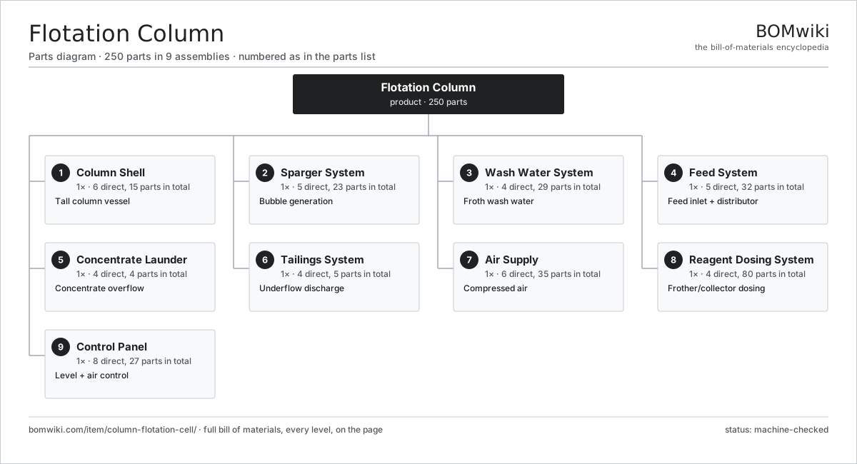
| # | Part | Qty | What it does |
|---|---|---|---|
| 1 | Column Shell 6 parts | 1× | Tall column vessel |
| 2 | Sparger System 5 parts | 1× | Bubble generation |
| 3 | Wash Water System 4 parts | 1× | Froth wash water |
| 4 | Feed System 5 parts | 1× | Feed inlet + distributor |
| 5 | Concentrate Launder 4 parts | 1× | Concentrate overflow |
| 6 | Tailings System 4 parts | 1× | Underflow discharge |
| 7 | Air Supply 6 parts | 1× | Compressed air |
| 8 | Reagent Dosing System 4 parts | 1× | Frother/collector dosing |
| 9 | Control Panel 8 parts | 1× | Level + air control |
3D model
No 3D model yet. Have a CAD file of this? Add a 3D model — STL renders right on this page; STEP, FreeCAD, and OpenSCAD sources are welcome too (openly licensed, like all 3D models on BOMwiki).
Build & assembly graph
expand / collapse · shared sub-assemblies converge · links to related products · est. labourTap an assembly to expand/collapse · tap a part to open it · use “Open page” for any node · drag to pan, scroll to zoom.
Bill of materials for Flotation Column
9 top-level lines · 80 rows shown · 250 parts total · indented to 3 levels| # | Item / sub-assembly | Part no. | Qty/assy | Ext. qty | Parts | Type |
|---|---|---|---|---|---|---|
| 1 | Column Shell 6 parts | column-flotation-cell-column-shell | 1× | 1 | 15 | assembly |
| 1.1 | Shell Section | column-flotation-cell-shell-section | 4× | 4 | · | part |
| 1.2 | Shell Liner | column-flotation-cell-shell-liner | 4× | 4 | · | part |
| 1.3 | Support Frame | column-flotation-cell-support-frame | 1× | 1 | · | part |
| 1.4 | Access Ladder & Platform | column-flotation-cell-access-ladder | 1× | 1 | · | part |
| 1.5 | Fastener Set | fastener-set | 1× | 1 | · | part |
| 1.6 | O-Ring Set | oring-set | 4× | 4 | · | part |
| 2 | Sparger System 5 parts | column-flotation-cell-sparger-system | 1× | 1 | 23 | assembly |
| 2.1 | Sparger | column-flotation-cell-sparger | 8× | 8 | · | part |
| 2.2 | Sparger Manifold | column-flotation-cell-sparger-manifold | 1× | 1 | · | part |
| 2.3 | Air-Water Mixing Tee | column-flotation-cell-mixing-tee | 4× | 4 | · | part |
| 2.4 | Pressure Sensor | pressure-sensor | 2× | 2 | · | part |
| 2.5 | O-Ring Set | oring-set | 8× | 8 | · | part |
| 3 | Wash Water System 4 parts | column-flotation-cell-wash-water-system | 1× | 1 | 29 | assembly |
| 3.1 | Wash Water Distributor | column-flotation-cell-wash-distributor | 1× | 1 | · | part |
| 3.2 | Wash Water Pump 5 parts | column-flotation-cell-wash-pump | 1× | 1 | 26 | assembly |
| 3.2.1 | Stator Assembly 3 parts + deeper › | stator-assembly | 1× | 1 | 3 | assembly |
| 3.2.2 | Rotor Assembly 4 parts + deeper › | rotor-assembly | 1× | 1 | 19 | assembly |
| 3.2.3 | Pump Impeller | column-flotation-cell-pump-impeller | 1× | 1 | · | part |
| 3.2.4 | Ball Bearing | ball-bearing | 2× | 2 | · | part |
| 3.2.5 | Oil Seal | oil-seal | 1× | 1 | · | part |
| 3.3 | Flow Meter | column-flotation-cell-flow-meter | 1× | 1 | · | part |
| 3.4 | Control Valve | column-flotation-cell-control-valve | 1× | 1 | · | part |
| 4 | Feed System 5 parts | column-flotation-cell-feed-system | 1× | 1 | 32 | assembly |
| 4.1 | Feed Inlet Box | column-flotation-cell-feed-inlet | 1× | 1 | · | part |
| 4.2 | Feed Distributor | column-flotation-cell-feed-distributor | 1× | 1 | · | part |
| 4.3 | Slurry Feed Pump 6 parts | column-flotation-cell-feed-pump | 1× | 1 | 28 | assembly |
| 4.3.1 | Stator Assembly 3 parts + deeper › | stator-assembly | 1× | 1 | 3 | assembly |
| 4.3.2 | Rotor Assembly 4 parts + deeper › | rotor-assembly | 1× | 1 | 19 | assembly |
| 4.3.3 | Pump Impeller | column-flotation-cell-pump-impeller | 1× | 1 | · | part |
| 4.3.4 | Shell Liner | column-flotation-cell-shell-liner | 1× | 1 | · | part |
| 4.3.5 | Ball Bearing | ball-bearing | 2× | 2 | · | part |
| 4.3.6 | Oil Seal | oil-seal | 2× | 2 | · | part |
| 4.4 | Flow Meter | column-flotation-cell-flow-meter | 1× | 1 | · | part |
| 4.5 | Shell Liner | column-flotation-cell-shell-liner | 1× | 1 | · | part |
| 5 | Concentrate Launder 4 parts | column-flotation-cell-launder | 1× | 1 | 4 | assembly |
| 5.1 | Launder Trough | column-flotation-cell-launder-trough | 1× | 1 | · | part |
| 5.2 | Froth Crowder | column-flotation-cell-froth-crowder | 1× | 1 | · | part |
| 5.3 | Concentrate Pipe | column-flotation-cell-concentrate-pipe | 1× | 1 | · | part |
| 5.4 | Shell Liner | column-flotation-cell-shell-liner | 1× | 1 | · | part |
| 6 | Tailings System 4 parts | column-flotation-cell-tailings-system | 1× | 1 | 5 | assembly |
| 6.1 | Tailings Outlet Cone | column-flotation-cell-tailings-outlet | 1× | 1 | · | part |
| 6.2 | Control Valve | column-flotation-cell-control-valve | 1× | 1 | · | part |
| 6.3 | Interface Level Sensor | column-flotation-cell-level-sensor | 2× | 2 | · | part |
| 6.4 | Flow Meter | column-flotation-cell-flow-meter | 1× | 1 | · | part |
| 7 | Air Supply 6 parts | column-flotation-cell-air-supply | 1× | 1 | 35 | assembly |
| 7.1 | Air Compressor 5 parts | column-flotation-cell-air-compressor | 1× | 1 | 29 | assembly |
| 7.1.1 | Stator Assembly 3 parts + deeper › | stator-assembly | 1× | 1 | 3 | assembly |
| 7.1.2 | Rotor Assembly 4 parts + deeper › | rotor-assembly | 1× | 1 | 19 | assembly |
| 7.1.3 | Screw Air End | column-flotation-cell-screw-element | 1× | 1 | · | part |
| 7.1.4 | Ball Bearing | ball-bearing | 4× | 4 | · | part |
| 7.1.5 | Oil Seal | oil-seal | 2× | 2 | · | part |
| 7.2 | Air Receiver | column-flotation-cell-air-receiver | 1× | 1 | · | part |
| 7.3 | Air Filter/Dryer | column-flotation-cell-air-filter | 1× | 1 | · | part |
| 7.4 | Control Valve | column-flotation-cell-control-valve | 1× | 1 | · | part |
| 7.5 | Flow Meter | column-flotation-cell-flow-meter | 1× | 1 | · | part |
| 7.6 | Pressure Sensor | pressure-sensor | 2× | 2 | · | part |
| 8 | Reagent Dosing System 4 parts | column-flotation-cell-reagent-system | 1× | 1 | 80 | assembly |
| 8.1 | Reagent Tank | column-flotation-cell-reagent-tank | 2× | 2 | · | part |
| 8.2 | Dosing Pump 4 parts | column-flotation-cell-dosing-pump | 2× | 2 | 25 | assembly |
| 8.2.1 | Stator Assembly 3 parts + deeper › | stator-assembly | 1× | 2 | 3 | assembly |
| 8.2.2 | Rotor Assembly 4 parts + deeper › | rotor-assembly | 1× | 2 | 19 | assembly |
| 8.2.3 | Pump Diaphragm | column-flotation-cell-diaphragm | 1× | 2 | · | part |
| 8.2.4 | O-Ring Set | oring-set | 2× | 4 | · | part |
| 8.3 | Tank Mixer 5 parts | column-flotation-cell-mixer | 1× | 1 | 26 | assembly |
| 8.3.1 | Stator Assembly 3 parts + deeper › | stator-assembly | 1× | 1 | 3 | assembly |
| 8.3.2 | Rotor Assembly 4 parts + deeper › | rotor-assembly | 1× | 1 | 19 | assembly |
| 8.3.3 | Gearbox Housing | gearbox-housing | 1× | 1 | · | part |
| 8.3.4 | Helical Gear Pair | gear-pair | 1× | 1 | · | part |
| 8.3.5 | Ball Bearing | ball-bearing | 2× | 2 | · | part |
| 8.4 | Flow Meter | column-flotation-cell-flow-meter | 2× | 2 | · | part |
| 9 | Control Panel 8 parts | column-flotation-cell-control-panel | 1× | 1 | 27 | assembly |
| 9.1 | Bare PCB | pcb-bare | 1× | 1 | · | part |
| 9.2 | Microcontroller | mcu | 1× | 1 | · | part |
| 9.3 | Relay | relay | 8× | 8 | · | part |
| 9.4 | Interface Level Sensor | column-flotation-cell-level-sensor | 1× | 1 | · | part |
| 9.5 | Pressure Sensor | pressure-sensor | 2× | 2 | · | part |
| 9.6 | Wire Bundle | wire-bundle | 1× | 1 | · | part |
| 9.7 | Connector | connector | 12× | 12 | · | part |
| 9.8 | Power Supply | power-supply | 1× | 1 | · | part |
Related products
same domain, ranked by shared parts Gravity Concentrating Table
184 parts · shares 12 with this page
Mechanized Scaling Rig
530 parts · shares 12 with this page
Gravity Concentrating Table
184 parts · shares 12 with this page
Mechanized Scaling Rig
530 parts · shares 12 with this page
 Mineral Jig Concentrator
145 parts · shares 12 with this page
Paste Backfill Plant
474 parts · shares 12 with this page
Mineral Jig Concentrator
145 parts · shares 12 with this page
Paste Backfill Plant
474 parts · shares 12 with this page
 Tailings Filter Press
1,088 parts · shares 12 with this page
Tailings Filter Press
1,088 parts · shares 12 with this page
 Carbon Regeneration Kiln
141 parts · shares 11 with this page
Carbon Regeneration Kiln
141 parts · shares 11 with this page
Sourcing: possible vendors
Prices, MOQ, and lead times are algorithmic estimates, not quotes, and not claims about these companies. Company mappings are curated by keyword; est. price band $200k–$5M. How estimates work| Vendor | HQ | Specialty | MOQ | Lead time |
|---|---|---|---|---|
| caterpillar.com ↗ | Irving, US | Construction & mining equipment | made to order | 20–36 wks |
|
🇯🇵Komatsu
komatsu.com ↗
|
Tokyo, JP | Construction & mining equipment | made to order | 20–36 wks |
|
🇸🇪Sandvik
rocktechnology.sandvik ↗
|
Stockholm, SE | Mining & rock technology | made to order | 20–36 wks |
|
🇸🇪Epiroc
epiroc.com ↗
|
Stockholm, SE | Mining & drilling equipment | made to order | 20–36 wks |
|
🇫🇮Metso
metso.com ↗
|
Helsinki, FI | Crushing & minerals processing | made to order | 20–36 wks |
994-word article