Overburden Conveyor Bridge
ProductOverview
An overburden conveyor bridge spans an open pit and carries stripped waste rock straight across it, from the side being mined to the spoil side, without trucks. In soft-rock lignite mining the layer of soil and rock over the coal seam, the overburden, is enormous in volume but worthless, so the cheapest way to move it is to lift it onto a belt and fly it across the pit in one continuous span. A conveyor bridge is among the largest mobile machines ever built, with a span of hundreds of metres riding on crawlers and weighing many thousands of tonnes, advancing slowly along the working face as the mine progresses.
The machine is a long Bridge Truss carrying a Conveyor Line, supported at each end by a Receiving Car and a Discharge Car that ride on Crawler Travel Set travel sets. A Discharge Boom throws the spoil off the far end, while a Electrical System system and a Operator Cab coordinate the whole machine.
How it works
Excavators or a spreader feed overburden onto the bridge at the Receiving Car. The Feed Hopper and Transfer Chute guide the stream onto the belt, which runs the length of the truss at several metres per second and discharges over the Discharge Car onto the spoil side. Because the two ends sit on opposite walls of a moving pit, each end travels on its own crawlers and the truss is free to pivot relative to each car through a Pivot Bearing, so the span can follow the curving advance of the face without binding. The whole bridge inches forward continuously as the digging side advances, a few metres per minute at most.
The conveyor line
The Conveyor Line is the working heart of the bridge. A single Conveyor Belt of steel-cord rubber, up to three metres wide, runs the full span. It is supported on its loaded run by hundreds of Carrying Idler trough idlers, each a set of three Idler Roll rolls on a Idler Frame, and on its empty return by Return Idler flat idlers. The belt is driven by Drive Pulley pulleys at one or more Drive Station stations, each with a Belt Drive Motor motor, a Gearbox Housing reduction, a Fluid Coupling fluid coupling to ease starting, and a Backstop to stop a loaded incline running backward. Bend Pulley pulleys turn the belt path.
Belt tension
A belt this long stretches under load and with temperature, so it needs constant tensioning. The Belt Take-Up does this with a movable Take-Up Pulley on a Take-Up Carriage, pulled by a Take-Up Winch. Too little tension and the belt slips at the drive; too much and the splices and idlers suffer. The take-up keeps tension in the right window automatically as conditions change over a shift.
Travelling on crawlers
The bridge cannot stand on fixed footings because the pit it spans is always moving, so it rides on Crawler Travel Set crawler sets. Each set runs Crawler Track tracks driven by Travel Motor motors through Gearbox Housing gearboxes, with a Steering Cylinder to steer it along the bench and Leveling Cylinder cylinders to level the structure on uneven ground. Steering and speed of every set must be coordinated so the long span is never twisted or dragged sideways, which is the main control problem of running the machine.
Discharging the spoil
At the far end the Discharge Boom discharge boom reaches out over the spoil side. The Boom Truss cantilever, kept in balance by the Counterweight on the Discharge Car, carries a short Boom Belt and Tripper Pulley pulleys that lift the belt to throw the material through a Discharge Chute onto the growing pile. The boom can slew on its Boom Slew Ring to spread the spoil evenly rather than dumping it all in one heap.
Power, control, and operation
The bridge runs on grid power through a Cable Reel that pays out a trailing cable as the machine advances. A Transformer steps the voltage down, a Drive Cabinet feeds the belt and travel motors with variable-speed drives, and a Control System synchronizes the crawler sets and protects the belt against overload, misalignment, and slip. The operator works from the Operator Cab at a Control Desk with LCD Panel displays of belt load, crawler steering, and boom position. A conveyor bridge replaces a large fleet of haul trucks for cross-pit waste movement, runs on cheaper grid power, and works continuously, which is why these machines remain central to large lignite operations despite their cost and the engineering needed to keep a span of that size moving as a single coordinated structure.
Overburden Conveyor Bridge parts and their functions
8 top-level parts · 6,684 parts in total · full bill of materials below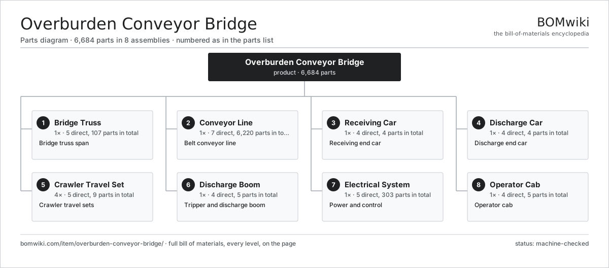
| # | Part | Qty | What it does |
|---|---|---|---|
| 1 | Bridge Truss 5 parts | 1× | Bridge truss span |
| 2 | Conveyor Line 7 parts | 1× | Belt conveyor line |
| 3 | Receiving Car 4 parts | 1× | Receiving end car |
| 4 | Discharge Car 4 parts | 1× | Discharge end car |
| 5 | Crawler Travel Set 5 parts | 4× | Crawler travel sets |
| 6 | Discharge Boom 4 parts | 1× | Tripper and discharge boom |
| 7 | Electrical System 5 parts | 1× | Power and control |
| 8 | Operator Cab 4 parts | 1× | Operator cab |
3D model
No 3D model yet. Have a CAD file of this? Add a 3D model — STL renders right on this page; STEP, FreeCAD, and OpenSCAD sources are welcome too (openly licensed, like all 3D models on BOMwiki).
Build & assembly graph
expand / collapse · shared sub-assemblies converge · links to related products · est. labourTap an assembly to expand/collapse · tap a part to open it · use “Open page” for any node · drag to pan, scroll to zoom.
Bill of materials for Overburden Conveyor Bridge
8 top-level lines · 65 rows shown · 6,684 parts total · indented to 3 levels| # | Item / sub-assembly | Part no. | Qty/assy | Ext. qty | Parts | Type |
|---|---|---|---|---|---|---|
| 1 | Bridge Truss 5 parts | overburden-conveyor-bridge-truss | 1× | 1 | 107 | assembly |
| 1.1 | Main Chord | overburden-conveyor-bridge-chord | 4× | 4 | · | part |
| 1.2 | Lattice Diagonal | overburden-conveyor-bridge-diagonal | 40× | 40 | · | part |
| 1.3 | Node Gusset | overburden-conveyor-bridge-node-gusset | 60× | 60 | · | part |
| 1.4 | Inspection Walkway | overburden-conveyor-bridge-walkway | 2× | 2 | · | part |
| 1.5 | Fastener Set | fastener-set | 1× | 1 | · | part |
| 2 | Conveyor Line 7 parts | overburden-conveyor-bridge-conveyor-line | 1× | 1 | 6,220 | assembly |
| 2.1 | Conveyor Belt | overburden-conveyor-bridge-belt | 1× | 1 | · | part |
| 2.2 | Carrying Idler 3 parts | overburden-conveyor-bridge-carry-idler | 600× | 600 | 10 | assembly |
| 2.2.1 | Idler Roll | overburden-conveyor-bridge-idler-roll | 3× | 1,800 | · | part |
| 2.2.2 | Idler Frame | overburden-conveyor-bridge-idler-bracket | 1× | 600 | · | part |
| 2.2.3 | Ball Bearing | ball-bearing | 6× | 3,600 | · | part |
| 2.3 | Return Idler | overburden-conveyor-bridge-return-idler | 200× | 200 | · | part |
| 2.4 | Drive Pulley | overburden-conveyor-bridge-drive-pulley | 2× | 2 | · | part |
| 2.5 | Bend Pulley | overburden-conveyor-bridge-bend-pulley | 4× | 4 | · | part |
| 2.6 | Drive Station 5 parts | overburden-conveyor-bridge-drive-station | 2× | 2 | 5 | assembly |
| 2.6.1 | Belt Drive Motor | overburden-conveyor-bridge-belt-motor | 1× | 2 | · | part |
| 2.6.2 | Gearbox Housing | gearbox-housing | 1× | 2 | · | part |
| 2.6.3 | Helical Gear Pair | gear-pair | 1× | 2 | · | part |
| 2.6.4 | Fluid Coupling | overburden-conveyor-bridge-coupling | 1× | 2 | · | part |
| 2.6.5 | Backstop | overburden-conveyor-bridge-backstop | 1× | 2 | · | part |
| 2.7 | Belt Take-Up 3 parts | overburden-conveyor-bridge-takeup | 1× | 1 | 3 | assembly |
| 2.7.1 | Take-Up Pulley | overburden-conveyor-bridge-takeup-pulley | 1× | 1 | · | part |
| 2.7.2 | Take-Up Winch | overburden-conveyor-bridge-takeup-winch | 1× | 1 | · | part |
| 2.7.3 | Take-Up Carriage | overburden-conveyor-bridge-takeup-carriage | 1× | 1 | · | part |
| 3 | Receiving Car 4 parts | overburden-conveyor-bridge-receiving-car | 1× | 1 | 4 | assembly |
| 3.1 | Feed Hopper | overburden-conveyor-bridge-feed-hopper | 1× | 1 | · | part |
| 3.2 | Transfer Chute | overburden-conveyor-bridge-feed-chute | 1× | 1 | · | part |
| 3.3 | Car Frame | overburden-conveyor-bridge-car-frame | 1× | 1 | · | part |
| 3.4 | Pivot Bearing | overburden-conveyor-bridge-pivot-bearing | 1× | 1 | · | part |
| 4 | Discharge Car 4 parts | overburden-conveyor-bridge-discharge-car | 1× | 1 | 4 | assembly |
| 4.1 | Car Frame | overburden-conveyor-bridge-car-frame | 1× | 1 | · | part |
| 4.2 | Pivot Bearing | overburden-conveyor-bridge-pivot-bearing | 1× | 1 | · | part |
| 4.3 | Boom Slew Ring | overburden-conveyor-bridge-slew-ring | 1× | 1 | · | part |
| 4.4 | Counterweight | overburden-conveyor-bridge-counterweight | 1× | 1 | · | part |
| 5 | Crawler Travel Set 5 parts | overburden-conveyor-bridge-crawler-set | 4× | 4 | 9 | assembly |
| 5.1 | Crawler Track | overburden-conveyor-bridge-crawler-track | 2× | 8 | · | part |
| 5.2 | Travel Motor | overburden-conveyor-bridge-travel-motor | 2× | 8 | · | part |
| 5.3 | Gearbox Housing | gearbox-housing | 2× | 8 | · | part |
| 5.4 | Steering Cylinder | overburden-conveyor-bridge-steer-cylinder | 1× | 4 | · | part |
| 5.5 | Leveling Cylinder | overburden-conveyor-bridge-level-cylinder | 2× | 8 | · | part |
| 6 | Discharge Boom 4 parts | overburden-conveyor-bridge-tripper | 1× | 1 | 5 | assembly |
| 6.1 | Boom Truss | overburden-conveyor-bridge-boom-truss | 1× | 1 | · | part |
| 6.2 | Tripper Pulley | overburden-conveyor-bridge-tripper-pulley | 2× | 2 | · | part |
| 6.3 | Discharge Chute | overburden-conveyor-bridge-discharge-chute | 1× | 1 | · | part |
| 6.4 | Boom Belt | overburden-conveyor-bridge-boom-conveyor | 1× | 1 | · | part |
| 7 | Electrical System 5 parts | overburden-conveyor-bridge-electrical | 1× | 1 | 303 | assembly |
| 7.1 | Cable Reel | overburden-conveyor-bridge-cable-reel | 1× | 1 | · | part |
| 7.2 | Transformer | overburden-conveyor-bridge-transformer | 1× | 1 | · | part |
| 7.3 | Drive Cabinet 4 parts | overburden-conveyor-bridge-drive-cabinet | 1× | 1 | 26 | assembly |
| 7.3.1 | Bare PCB | pcb-bare | 4× | 4 | · | part |
| 7.3.2 | Microcontroller | mcu | 4× | 4 | · | part |
| 7.3.3 | Relay | relay | 16× | 16 | · | part |
| 7.3.4 | Power Supply | power-supply | 2× | 2 | · | part |
| 7.4 | Control System 4 parts | overburden-conveyor-bridge-plc | 1× | 1 | 274 | assembly |
| 7.4.1 | Bare PCB | pcb-bare | 2× | 2 | · | part |
| 7.4.2 | Microcontroller | mcu | 2× | 2 | · | part |
| 7.4.3 | SMD Passive (R/C/L) | smd-passives | 220× | 220 | · | part |
| 7.4.4 | Connector | connector | 50× | 50 | · | part |
| 7.5 | Power Supply | power-supply | 1× | 1 | · | part |
| 8 | Operator Cab 4 parts | overburden-conveyor-bridge-control-cab | 1× | 1 | 5 | assembly |
| 8.1 | Cab Shell | overburden-conveyor-bridge-cab-shell | 1× | 1 | · | part |
| 8.2 | Operator Seat | overburden-conveyor-bridge-seat | 1× | 1 | · | part |
| 8.3 | LCD Panel | lcd-panel | 2× | 2 | · | part |
| 8.4 | Control Desk | overburden-conveyor-bridge-control-desk | 1× | 1 | · | part |
Related products
same domain, ranked by shared parts Carbon Regeneration Kiln
141 parts · shares 4 with this page
Carbon Regeneration Kiln
141 parts · shares 4 with this page
 Electric Rope Shovel
507 parts · shares 4 with this page
Electric Rope Shovel
507 parts · shares 4 with this page
 Gravity Concentrating Table
184 parts · shares 4 with this page
Gravity Concentrating Table
184 parts · shares 4 with this page
 In-Pit Crushing and Conveying System
8,200 parts · shares 4 with this page
Mechanized Scaling Rig
530 parts · shares 4 with this page
In-Pit Crushing and Conveying System
8,200 parts · shares 4 with this page
Mechanized Scaling Rig
530 parts · shares 4 with this page
 Mineral Jig Concentrator
145 parts · shares 4 with this page
Mineral Jig Concentrator
145 parts · shares 4 with this page
Sourcing: possible vendors
Prices, MOQ, and lead times are algorithmic estimates, not quotes, and not claims about these companies. Company mappings are curated by keyword; est. price band $200k–$5M. How estimates work| Vendor | HQ | Specialty | MOQ | Lead time |
|---|---|---|---|---|
| caterpillar.com ↗ | Irving, US | Construction & mining equipment | made to order | 20–36 wks |
|
🇯🇵Komatsu
komatsu.com ↗
|
Tokyo, JP | Construction & mining equipment | made to order | 20–36 wks |
|
🇸🇪Sandvik
rocktechnology.sandvik ↗
|
Stockholm, SE | Mining & rock technology | made to order | 20–36 wks |
|
🇸🇪Epiroc
epiroc.com ↗
|
Stockholm, SE | Mining & drilling equipment | made to order | 20–36 wks |
|
🇫🇮Metso
metso.com ↗
|
Helsinki, FI | Crushing & minerals processing | made to order | 20–36 wks |
908-word article