Auxiliary Mine Fan
ProductOverview
An auxiliary mine fan ventilates the dead-end workings that the main mine ventilation circuit cannot reach. A mine's primary fans move enormous volumes of air through the through-going airways, but a development heading being driven into solid rock is a blind tube: air will not flow into it on its own. The auxiliary fan, working with a length of ducting, forces fresh air to the face or draws contaminated air away from it. This is what makes it safe for people to work at the end of a heading, clearing diesel exhaust, blasting fumes, dust, and any gas seeping from the rock, and supplying the oxygen the crew and equipment need.
The fan itself is an axial machine: a bladed Impeller Assembly spinning inside a cylindrical Fan Casing, driven by a flameproof Drive Motor. Air enters along the axis, is accelerated by the blades, and leaves along the same axis into the Ducting that carries it down the heading. Because mines are noise-sensitive and explosion-risk environments, the design wraps this simple aerodynamic core in Silencer units, a robust Skid Frame, and a protective Control Panel panel.
Forcing, exhausting, and overlap
Auxiliary ventilation is run in one of three modes, and the fan is selected to suit. In forcing ventilation the fan pushes fresh air through the duct to the face, where it scours the working area and the stale air returns along the open heading. This delivers clean air right to the crew but lets contaminated return air travel back past them. In exhausting ventilation the fan pulls air out of the heading through the duct, drawing fresh air in along the open roadway; this clears blasting fumes well but needs rigid or spiral-reinforced duct that will not collapse under suction. An overlap system uses both, a forcing duct and an exhausting duct working together, for long or gassy headings. The same fan platform serves these modes with changes to ducting and fan position.
Impeller and motor
The Impeller Assembly is the working element. Aerofoil Aerofoil Blade units, of cast aluminum or glass-reinforced polymer, are set into a central Impeller Hub. Most auxiliary fans have adjustable blade pitch: each blade root turns on a Blade Pitch Bearing so the angle of attack can be set to match the duct length and the airflow needed. A steeper pitch moves more air against more resistance but draws more power, so pitch is tuned to the heading as it advances and the duct gets longer. The impeller is balanced with trim Balance Weight pieces because it spins fast and any imbalance shortens bearing life. It is driven directly by a Drive Motor, a flameproof induction motor whose Motor Housing is built to contain any internal spark, an essential feature where flammable gas may be present.
Casing, aerodynamics, and noise
The Fan Casing is a steel tube that houses the impeller and forms the airway. An Inlet Bellmouth bellmouth smooths air into the blades, internal straightening vanes on the Motor Mount and Vanes remove the swirl the impeller imparts, and an Outlet Diffuser cone at the outlet recovers some of the air's velocity back into useful pressure. Axial fans are efficient but loud, and a heading concentrates the sound, so Silencer units fitted at the inlet and outlet pass the air through absorptive Acoustic Splitter splitters lined with sound-absorbing material. Bringing the noise down protects the hearing of crews who work near the fan for a full shift.
Frame and ducting
The fan and its silencers sit on a Skid Frame, a welded skid with Vibration Isolator mounts that keep vibration out of the structure and Lifting Lug points for moving the unit as the heading advances. The air is delivered by the Ducting system. Forcing duct is usually Flexible Duct, a coated fabric tube that packs flat for storage and inflates under pressure; exhausting duct must be rigid or spiral-reinforced Rigid Duct so it does not collapse under suction. Lengths are joined by Duct Coupling clamps and hung from the roof on Duct Hanger supports. Duct leakage is the main loss in the system: a long run of poorly sealed duct can lose most of the fan's output before it reaches the face, so duct quality and jointing matter as much as the fan rating.
Control and protection
The Control Panel panel starts and protects the fan. A Motor Starter, commonly a soft starter or variable frequency drive, brings the heavy impeller up to speed without a large inrush current and lets the airflow be matched to demand. An Overload Relay relay and motor Winding Thermistor guard the windings, and an Airflow Monitor confirms that air is actually flowing, because a fan that runs but moves no air, through a torn duct or a stalled blade pitch, gives a false sense of safety. The whole panel is housed in a sealed Panel Enclosure.
Selection and variants
Selecting a fan means matching its pressure-flow curve to the resistance of the duct run, which rises with length and falls with diameter. As a heading advances, operators either change blade pitch, add a second fan in series for more pressure, or run twin fans in parallel for more flow. Variants range from small single-stage fans for short development headings to twin-stage, high-pressure machines that push air through two kilometers of duct in long tunnels. Larger units may be diesel-driven where electrical reticulation has not yet reached the working area. Across the range the job is the same: keep a controlled stream of fresh air reaching the one part of the mine that the main circuit cannot serve by itself.
Auxiliary Mine Fan parts and their functions
7 top-level parts · 213 parts in total · full bill of materials below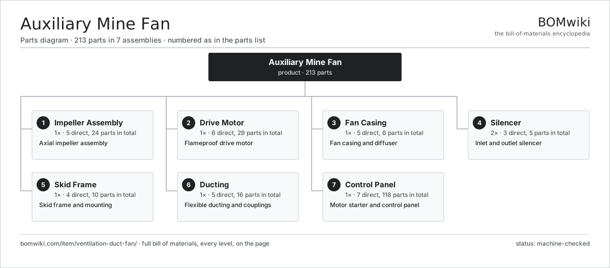
| # | Part | Qty | What it does |
|---|---|---|---|
| 1 | Impeller Assembly 5 parts | 1× | Axial impeller assembly |
| 2 | Drive Motor 6 parts | 1× | Flameproof drive motor |
| 3 | Fan Casing 5 parts | 1× | Fan casing and diffuser |
| 4 | Silencer 3 parts | 2× | Inlet and outlet silencer |
| 5 | Skid Frame 4 parts | 1× | Skid frame and mounting |
| 6 | Ducting 5 parts | 1× | Flexible ducting and couplings |
| 7 | Control Panel 7 parts | 1× | Motor starter and control panel |
3D model
No 3D model yet. Have a CAD file of this? Add a 3D model — STL renders right on this page; STEP, FreeCAD, and OpenSCAD sources are welcome too (openly licensed, like all 3D models on BOMwiki).
Build & assembly graph
expand / collapse · shared sub-assemblies converge · links to related products · est. labourTap an assembly to expand/collapse · tap a part to open it · use “Open page” for any node · drag to pan, scroll to zoom.
Bill of materials for Auxiliary Mine Fan
7 top-level lines · 57 rows shown · 213 parts total · indented to 3 levels| # | Item / sub-assembly | Part no. | Qty/assy | Ext. qty | Parts | Type |
|---|---|---|---|---|---|---|
| 1 | Impeller Assembly 5 parts | ventilation-duct-fan-impeller | 1× | 1 | 24 | assembly |
| 1.1 | Impeller Hub | ventilation-duct-fan-hub | 1× | 1 | · | part |
| 1.2 | Aerofoil Blade | ventilation-duct-fan-blade | 9× | 9 | · | part |
| 1.3 | Blade Pitch Bearing | ventilation-duct-fan-blade-bearing | 9× | 9 | · | part |
| 1.4 | Balance Weight | ventilation-duct-fan-balance-weight | 4× | 4 | · | part |
| 1.5 | Fastener Set | fastener-set | 1× | 1 | · | part |
| 2 | Drive Motor 6 parts | ventilation-duct-fan-motor | 1× | 1 | 29 | assembly |
| 2.1 | Stator Assembly 3 parts | stator-assembly | 1× | 1 | 3 | assembly |
| 2.1.1 | Stator Core (laminations) | stator-core | 1× | 1 | · | part |
| 2.1.2 | Copper Winding | copper-winding | 1× | 1 | · | part |
| 2.1.3 | Slot Insulation | stator-insulation | 1× | 1 | · | part |
| 2.2 | Rotor Assembly 4 parts | rotor-assembly | 1× | 1 | 19 | assembly |
| 2.2.1 | Rotor Shaft | rotor-shaft | 1× | 1 | · | part |
| 2.2.2 | Rotor Core | rotor-core | 1× | 1 | · | part |
| 2.2.3 | Neodymium Magnet | neodymium-magnet | 16× | 16 | · | part |
| 2.2.4 | Ball Bearing | ball-bearing | 1× | 1 | · | part |
| 2.3 | Motor Housing | ventilation-duct-fan-motor-housing | 1× | 1 | · | part |
| 2.4 | Ball Bearing | ball-bearing | 2× | 2 | · | part |
| 2.5 | Terminal Box | ventilation-duct-fan-terminal-box | 1× | 1 | · | part |
| 2.6 | Winding Thermistor | ventilation-duct-fan-thermistor | 3× | 3 | · | part |
| 3 | Fan Casing 5 parts | ventilation-duct-fan-casing | 1× | 1 | 6 | assembly |
| 3.1 | Casing Tube | ventilation-duct-fan-casing-tube | 1× | 1 | · | part |
| 3.2 | Motor Mount and Vanes | ventilation-duct-fan-motor-mount | 1× | 1 | · | part |
| 3.3 | Outlet Diffuser | ventilation-duct-fan-diffuser | 1× | 1 | · | part |
| 3.4 | Inlet Bellmouth | ventilation-duct-fan-inlet-cone | 1× | 1 | · | part |
| 3.5 | Guard Grille | ventilation-duct-fan-guard | 2× | 2 | · | part |
| 4 | Silencer 3 parts | ventilation-duct-fan-silencer | 2× | 2 | 5 | assembly |
| 4.1 | Silencer Shell | ventilation-duct-fan-silencer-shell | 1× | 2 | · | part |
| 4.2 | Acoustic Splitter | ventilation-duct-fan-acoustic-pod | 3× | 6 | · | part |
| 4.3 | Acoustic Liner | ventilation-duct-fan-acoustic-liner | 1× | 2 | · | part |
| 5 | Skid Frame 4 parts | ventilation-duct-fan-frame | 1× | 1 | 10 | assembly |
| 5.1 | Skid Base | ventilation-duct-fan-skid | 1× | 1 | · | part |
| 5.2 | Vibration Isolator | ventilation-duct-fan-isolator | 4× | 4 | · | part |
| 5.3 | Lifting Lug | ventilation-duct-fan-lifting-lug | 4× | 4 | · | part |
| 5.4 | Fastener Set | fastener-set | 1× | 1 | · | part |
| 6 | Ducting 5 parts | ventilation-duct-fan-duct | 1× | 1 | 16 | assembly |
| 6.1 | Flexible Duct | ventilation-duct-fan-flex-duct | 1× | 1 | · | part |
| 6.2 | Rigid Duct | ventilation-duct-fan-rigid-duct | 1× | 1 | · | part |
| 6.3 | Duct Coupling | ventilation-duct-fan-coupling | 4× | 4 | · | part |
| 6.4 | Duct Hanger | ventilation-duct-fan-duct-hanger | 8× | 8 | · | part |
| 6.5 | Anti-Collapse Spiral | ventilation-duct-fan-spiral-spring | 2× | 2 | · | part |
| 7 | Control Panel 7 parts | ventilation-duct-fan-control | 1× | 1 | 118 | assembly |
| 7.1 | Motor Starter 4 parts | ventilation-duct-fan-starter | 1× | 1 | 63 | assembly |
| 7.1.1 | Bare PCB | pcb-bare | 1× | 1 | · | part |
| 7.1.2 | Microcontroller | mcu | 1× | 1 | · | part |
| 7.1.3 | Power Supply | power-supply | 1× | 1 | · | part |
| 7.1.4 | SMD Passive (R/C/L) | smd-passives | 60× | 60 | · | part |
| 7.2 | Main Contactor | ventilation-duct-fan-contactor | 1× | 1 | · | part |
| 7.3 | Overload Relay | ventilation-duct-fan-overload | 1× | 1 | · | part |
| 7.4 | Airflow Monitor 4 parts | ventilation-duct-fan-monitor | 1× | 1 | 43 | assembly |
| 7.4.1 | Pressure Sensor | pressure-sensor | 1× | 1 | · | part |
| 7.4.2 | Bare PCB | pcb-bare | 1× | 1 | · | part |
| 7.4.3 | Microcontroller | mcu | 1× | 1 | · | part |
| 7.4.4 | SMD Passive (R/C/L) | smd-passives | 40× | 40 | · | part |
| 7.5 | Panel Enclosure | ventilation-duct-fan-enclosure | 1× | 1 | · | part |
| 7.6 | Wire Bundle | wire-bundle | 1× | 1 | · | part |
| 7.7 | Connector | connector | 8× | 8 | · | part |
Related products
same domain, ranked by shared parts Carbon Regeneration Kiln
141 parts · shares 10 with this page
Double Roll Crusher
214 parts · shares 10 with this page
Carbon Regeneration Kiln
141 parts · shares 10 with this page
Double Roll Crusher
214 parts · shares 10 with this page
 Electrowinning Cell
347 parts · shares 10 with this page
Flotation Reagent Dosing Skid
198 parts · shares 10 with this page
Electrowinning Cell
347 parts · shares 10 with this page
Flotation Reagent Dosing Skid
198 parts · shares 10 with this page
 Gold Elution Column
128 parts · shares 10 with this page
Gold Elution Column
128 parts · shares 10 with this page
 Gravity Concentrating Table
184 parts · shares 10 with this page
Gravity Concentrating Table
184 parts · shares 10 with this page
Sourcing: possible vendors
Prices, MOQ, and lead times are algorithmic estimates, not quotes, and not claims about these companies. Company mappings are curated by keyword; est. price band $200k–$5M. How estimates work| Vendor | HQ | Specialty | MOQ | Lead time |
|---|---|---|---|---|
| caterpillar.com ↗ | Irving, US | Construction & mining equipment | made to order | 20–36 wks |
|
🇯🇵Komatsu
komatsu.com ↗
|
Tokyo, JP | Construction & mining equipment | made to order | 20–36 wks |
|
🇸🇪Sandvik
rocktechnology.sandvik ↗
|
Stockholm, SE | Mining & rock technology | made to order | 20–36 wks |
|
🇸🇪Epiroc
epiroc.com ↗
|
Stockholm, SE | Mining & drilling equipment | made to order | 20–36 wks |
|
🇫🇮Metso
metso.com ↗
|
Helsinki, FI | Crushing & minerals processing | made to order | 20–36 wks |
1,029-word article