Capsule Coffee Machine
ProductOverview
A capsule coffee machine brews one cup at a time from a sealed, pre-measured pod. The user drops in a capsule, closes a lever, and presses a button; the machine pierces the pod, forces hot water through the grounds inside, and drains the brewed coffee into the cup below. Because the coffee dose, grind, and tamp are all fixed at the factory inside the capsule, the machine itself needs to do much less than a bean-to-cup unit. Its job reduces to four things: handling the capsule, heating water, pumping it through under pressure, and timing the shot.
The main subsystems are the Brew Head that pierces and seals the pod, the Water Circuit that delivers hot pressurised water, the Capsule Handling Mechanism that loads and ejects pods, and the Control Board that runs the cycle. The Housing and Water Tank complete the appliance. The result is a machine that is fast, clean, and forgiving, at the cost of relying on a proprietary consumable.
The brew head
The Brew Head is what makes capsule brewing work. A capsule arrives sealed on both faces, so the head must open it at the moment of brewing to keep the coffee fresh until then. When the head closes, the Injection Needle on the Injection Plate punctures the lid to admit water, while the spikes of the Extraction Plate tear the foil base from inside the brew chamber. The Capsule Holder cradles the pod and presses its rim against the Brew Head Seal, so that the entire pressure of the pump is contained within the capsule rather than leaking around it. Only the base of the pod is opened by the internal pressure pushing the foil onto the Piercer Spike Array, which is why a fresh pod stays airtight until it is actually brewed.
Water, pressure, and heat
Water is drawn from the Water Tank and raised to brewing pressure by the Vibration Pump. This is a solenoid-driven piston pump that pulses rapidly, and in capsule machines it commonly peaks near 19 bar. High pressure is needed because the coffee bed inside a capsule is dense and the brew time is short, so the water must be driven hard to extract flavour quickly. Heat comes from the Thermoblock Heater, an aluminium block with a cast-in Heating Element that warms water as it passes rather than keeping a tank hot. This is what lets a capsule machine reach brewing temperature in under half a minute from cold. An NTC Temperature Sensor regulates the block and a Thermal Fuse protects it against runaway heating. On the outflow, a Flow Restrictor holds back pressure just enough to whip the coffee into the layer of crema that capsule drinks are known for, and a Check Valve stops water draining back when the pump stops.
Loading and ejecting capsules
The Capsule Handling Mechanism turns a single lever pull into the whole mechanical sequence. The Loading Lever drives the Cam Linkage, a toggle that multiplies the user's effort into enough force to clamp the brew head shut and hold it against pump pressure. When the lever is lifted after brewing, the same linkage releases the head and the spent pod drops down the Ejection Ramp into the Used Capsule Bin. Storing several used capsules in a bin, rather than forcing the user to remove each one by hand, is part of what makes the machine quick to use for back-to-back cups. Return springs reset the lever and holder between cycles.
Control and electronics
The Control Board is deliberately simple. An Microcontroller reads the Brew Buttons buttons, switches the Heating Element through a Triac, runs the Vibration Pump through a Relay, and times each shot by volume or by a fixed run time. Many machines offer two or three preset cup sizes and let the user reprogram them by holding a button during a pour. The electronics also watch the thermoblock temperature so that brewing only begins once the water is hot, and they hold the pump off until then.
Housing, use, and variants
The Housing carries the Drip Tray and an adjustable Cup Stand so that both small espresso cups and tall mugs sit close under the Coffee Spout. Daily use is straightforward: fill the tank, drop a capsule in, brew, and lift the lever to discard it. Maintenance is light, mostly emptying the used-pod bin and drip tray and running an occasional descale to clear scale from the thermoblock and pump. Variants in the category differ mainly in capsule format and pressure: espresso-style machines run high pressure through small pods, while larger-format systems use lower pressure and bigger pods for filter-style coffee. The piercing brew head and flow-through heater are common to nearly all of them.
Capsule Coffee Machine parts and their functions
7 top-level parts · 123 parts in total · full bill of materials below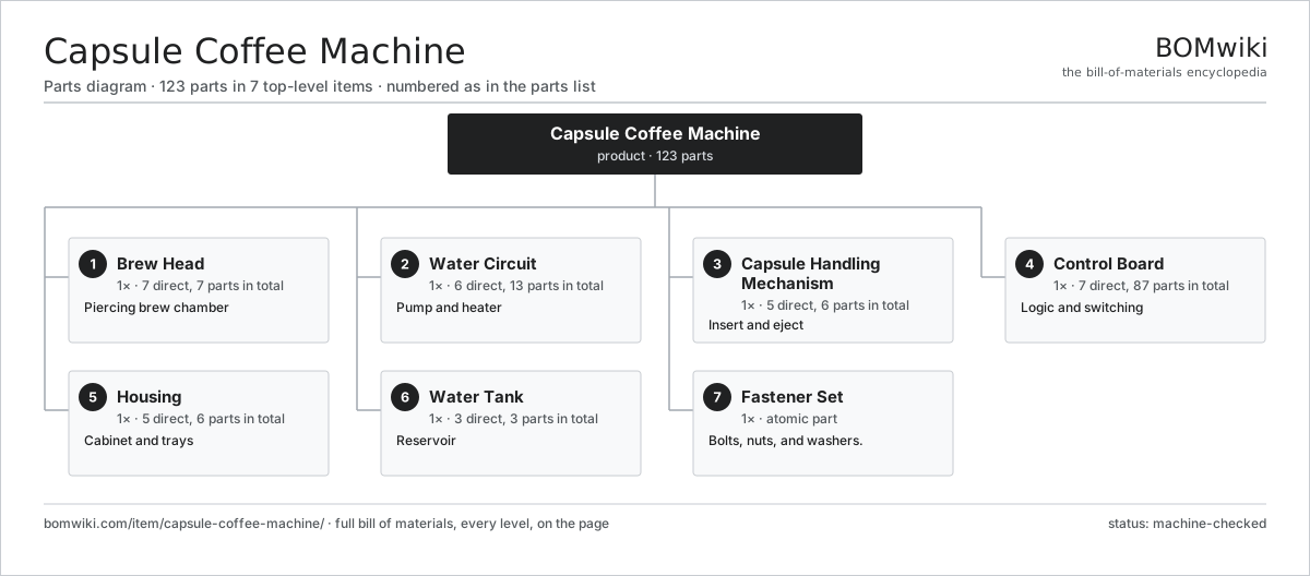
| # | Part | Qty | What it does |
|---|---|---|---|
| 1 | Brew Head 7 parts | 1× | Piercing brew chamber |
| 2 | Water Circuit 6 parts | 1× | Pump and heater |
| 3 | Capsule Handling Mechanism 5 parts | 1× | Insert and eject |
| 4 | Control Board 7 parts | 1× | Logic and switching |
| 5 | Housing 5 parts | 1× | Cabinet and trays |
| 6 | Water Tank 3 parts | 1× | Reservoir |
| 7 | Fastener Set | 1× | Bolts, nuts, and washers. |
3D model
No 3D model yet. Have a CAD file of this? Add a 3D model. STL renders right on this page; STEP, FreeCAD, and OpenSCAD sources are welcome too (openly licensed, like all 3D models on BOMwiki).
Build & assembly graph
expand / collapse · shared sub-assemblies converge · links to related products · est. labourTap an assembly to expand/collapse · tap a part to open it · use “Open page” for any node · drag to pan, scroll to zoom.
Bill of materials for Capsule Coffee Machine
7 top-level lines · 48 rows shown · 123 parts total · indented to 3 levels| # | Item / sub-assembly | Part no. | Qty/assy | Ext. qty | Parts | Type |
|---|---|---|---|---|---|---|
| 1 | Brew Head 7 parts | ccm-brew-head | 1× | 1 | 7 | assembly |
| 1.1 | Injection Plate | ccm-injection-plate | 1× | 1 | · | part |
| 1.2 | Extraction Plate | ccm-extraction-plate | 1× | 1 | · | part |
| 1.3 | Capsule Holder | ccm-capsule-holder | 1× | 1 | · | part |
| 1.4 | Injection Needle | ccm-injection-needle | 1× | 1 | · | part |
| 1.5 | Piercer Spike Array | ccm-piercer-spikes | 1× | 1 | · | part |
| 1.6 | Brew Head Seal | ccm-head-seal | 1× | 1 | · | part |
| 1.7 | O-Ring Set | oring-set | 1× | 1 | · | part |
| 2 | Water Circuit 6 parts | ccm-water-circuit | 1× | 1 | 13 | assembly |
| 2.1 | Vibration Pump 3 parts | ccm-vibration-pump | 1× | 1 | 3 | assembly |
| 2.1.1 | Pump Solenoid Coil | ccm-pump-coil | 1× | 1 | · | part |
| 2.1.2 | Pump Piston | ccm-pump-piston | 1× | 1 | · | part |
| 2.1.3 | Coil Spring | coil-spring | 1× | 1 | · | part |
| 2.2 | Thermoblock Heater 3 parts | ccm-thermoblock | 1× | 1 | 3 | assembly |
| 2.2.1 | Thermoblock Body | ccm-block-body | 1× | 1 | · | part |
| 2.2.2 | Heating Element | heating-element | 1× | 1 | · | part |
| 2.2.3 | NTC Temperature Sensor | ccm-ntc-sensor | 1× | 1 | · | part |
| 2.3 | Check Valve | ccm-check-valve | 1× | 1 | · | part |
| 2.4 | Flow Restrictor | ccm-flow-restrictor | 1× | 1 | · | part |
| 2.5 | Silicone Hose | ccm-silicone-hose | 4× | 4 | · | part |
| 2.6 | Thermal Fuse | thermal-fuse | 1× | 1 | · | part |
| 3 | Capsule Handling Mechanism 5 parts | ccm-capsule-handler | 1× | 1 | 6 | assembly |
| 3.1 | Loading Lever | ccm-load-lever | 1× | 1 | · | part |
| 3.2 | Cam Linkage | ccm-cam-linkage | 1× | 1 | · | part |
| 3.3 | Ejection Ramp | ccm-eject-ramp | 1× | 1 | · | part |
| 3.4 | Used Capsule Bin | ccm-used-bin | 1× | 1 | · | part |
| 3.5 | Coil Spring | coil-spring | 2× | 2 | · | part |
| 4 | Control Board 7 parts | ccm-control-board | 1× | 1 | 87 | assembly |
| 4.1 | Bare PCB | pcb-bare | 1× | 1 | · | part |
| 4.2 | Microcontroller | mcu | 1× | 1 | · | part |
| 4.3 | Brew Buttons | ccm-power-switch | 1× | 1 | · | part |
| 4.4 | Relay | relay | 2× | 2 | · | part |
| 4.5 | Triac | triac | 1× | 1 | · | part |
| 4.6 | SMD Passive (R/C/L) | smd-passives | 80× | 80 | · | part |
| 4.7 | Wire Bundle | wire-bundle | 1× | 1 | · | part |
| 5 | Housing 5 parts | ccm-housing | 1× | 1 | 6 | assembly |
| 5.1 | Cabinet Shell | ccm-cabinet-shell | 1× | 1 | · | part |
| 5.2 | Drip Tray 2 parts | ccm-drip-tray | 1× | 1 | 2 | assembly |
| 5.2.1 | Drip Tray Body | ccm-tray-body | 1× | 1 | · | part |
| 5.2.2 | Drip Grate | ccm-tray-grate | 1× | 1 | · | part |
| 5.3 | Cup Stand | ccm-cup-stand | 1× | 1 | · | part |
| 5.4 | Coffee Spout | ccm-spout | 1× | 1 | · | part |
| 5.5 | Sheet Metal Panel | sheet-panel | 1× | 1 | · | part |
| 6 | Water Tank 3 parts | ccm-water-tank | 1× | 1 | 3 | assembly |
| 6.1 | Tank Shell | ccm-tank-shell | 1× | 1 | · | part |
| 6.2 | Tank Outlet Valve | ccm-tank-valve | 1× | 1 | · | part |
| 6.3 | Tank Lid | ccm-tank-lid | 1× | 1 | · | part |
| 7 | Fastener Set | fastener-set | 1× | 1 | · | part |
Related products
same domain, ranked by shared parts Cotton Candy Machine
127 parts · shares 4 with this page
Super-Automatic Espresso Machine
293 parts · shares 6 with this page
Multi-Function Rice Cooker
200 parts · shares 4 with this page
Cotton Candy Machine
127 parts · shares 4 with this page
Super-Automatic Espresso Machine
293 parts · shares 6 with this page
Multi-Function Rice Cooker
200 parts · shares 4 with this page
 Espresso Machine
120 parts · shares 2 with this page
Espresso Machine
120 parts · shares 2 with this page
 Sous Vide Immersion Circulator
294 parts · shares 4 with this page
Stand Mixer
130 parts · shares 3 with this page
Sous Vide Immersion Circulator
294 parts · shares 4 with this page
Stand Mixer
130 parts · shares 3 with this page
Sourcing: possible vendors
Browse the supplier directory → Prices, MOQ, and lead times are algorithmic estimates, not quotes, and not claims about these companies. Company mappings are curated by keyword; est. price band $20–$600. How estimates work| Vendor | HQ | Specialty | MOQ | Lead time |
|---|---|---|---|---|
|
🇦🇺Breville
breville.com ↗
|
Sydney, AU | Kitchen appliances | 2,000 units | 6–10 wks |
| groupeseb.com ↗ | Écully, FR | Cookware & small appliances | 2,000 units | 6–10 wks |
| hamiltonbeach.com ↗ | Glen Allen, US | Small appliances | 2,000 units | 6–10 wks |
| panasonic.com ↗ | Osaka, JP | Electronics & appliances | 2,000 units | 6–10 wks |
|
🇨🇳Midea
midea.com ↗
|
Foshan, CN | Home appliances | 2,000 units | 6–10 wks |
823-word article