Masticating Juicer
ProductAlso known as: Slow Masticating Juicer
Overview
A masticating juicer extracts juice by crushing and pressing produce against a screen rather than shredding it on a spinning disc. A single tapered screw turns slowly inside a bowl, drawing produce in from the top, grinding it against a perforated screen, and squeezing the juice out while pushing the dry pulp toward a separate outlet. Because the screw turns at only tens of revolutions per minute, the juice picks up little air and little heat, so it oxidises slowly and keeps more flavour and colour than juice from a fast centrifugal machine. The trade is speed: feeding has to be patient, and produce usually needs cutting into pieces that fit the chute.
The machine is built around a slow, forceful drive. The Motor and Drive sits in the Motor Base and turns the Juicing Chamber chamber on top. Produce enters through the Feed Chute chute, juice and pulp leave through the Outlets, and the Collection Cups catch each stream. The Control runs the motor, and the Safety Interlock keeps it from running unless the bowl is locked in place.
Motor and gear reduction
The hard problem in a masticating juicer is making high torque at low speed. The AC Induction Motor is an AC induction motor that naturally spins near 1400 rpm, far too fast to press juice without tearing produce and heating it. The Motor and Drive solves this with a large reduction. A Worm and Worm Wheel on the motor shaft drives a bronze worm wheel for the first, largest step down, and a Helical Gear Pair takes a second step inside the Gearbox Housing. The combined ratio of roughly 36:1 to 50:1 brings the Output Shaft down to around 65 rpm while multiplying torque by the same factor. The worm stage is also close to self-locking, which helps the auger hold against the back-pressure of packed pulp. Inside the motor a Run Capacitor gives it starting torque, a Thermal Cutout protects the windings, and the Stator Assembly and Rotor Assembly turn on a pair of Ball Bearing supports. The gearbox shaft rides on more Ball Bearing units with two Oil Seal elements keeping grease in and juice out, and the Drive Coupling passes the torque up to the auger, disengaging on its own when the bowl lifts off.
Auger and screens
The Juicing Chamber chamber is where the work happens. The Juicing Auger is a conical Ultem screw whose flights grow shallower toward the front, so the space for produce shrinks as it advances and the material is squeezed harder against the screen. Ultem is used because it resists cracking under that pressure and tolerates repeated cleaning. The Fine Screen is a finely perforated stainless cylinder that gives clear juice from soft fruit and leafy greens, while the Coarse Screen passes more pulp for thicker juice. Swapping in the Blank Screen blocks the juice path entirely so the auger extrudes frozen fruit into a soft sorbet. A Wiper Blade turns with the auger and scrapes pulp off the screen so the perforations do not clog mid-batch. The whole stack closes inside the clear Juicing Bowl and is capped by the Bowl Cap, with an O-Ring Set sealing the joints so juice cannot weep out.
Feeding and outlets
Produce reaches the auger through the Feed Chute chute. A wide Feed Hopper holds cut produce, the Feed Chute Neck neck drops it onto the top of the auger, and the Food Pusher nudges stubborn pieces down without forcing the screw. A Anti-splash Flap stops the turning auger from splashing back up the chute. On the far side the two streams divide. Juice runs out the Juice Spout, which a Drip-stop Cap can close so juice blends in the bowl before pouring, and dry pulp is pushed out the Pulp Port. The Pulp Pressure Knob tightens that port to raise back-pressure, which presses the pulp drier and lifts the yield, at the cost of a higher chance of jamming on fibrous produce. An O-Ring Set seals the outlet fittings against drips.
Control and safety
The Control keeps the motor simple to run. A three-position Rocker Switch selects forward run, off, or a momentary reverse that backs the auger out when produce wedges and stalls it. The Control Board carries an Microcontroller on a Bare PCB with SMD Passive (R/C/L), reads a Current Shunt to sense a stalled motor, and switches the windings through a Relay; a Wire Bundle and its Connector links tie the board to the switch and motor, fed by the Power Cord. Safety rests on the Safety Interlock. A Interlock Tab on the bowl presses the Interlock Switch only when the bowl is twisted into its locked position, so the motor cannot turn the exposed coupling with the bowl off. A Coil Spring returns the switch when the bowl is removed.
Use and care
Masticating juicers suit users who want high yield and slow oxidation and do not mind a slower routine. They handle leafy greens, wheatgrass, and soft fruit better than centrifugal machines because the slow press wrings fibre that a spinning basket throws aside half-wet. Hard produce like carrots and beets juices well too, though it should be cut small to avoid stalling the Juicing Auger. Cleaning is the main chore: pulp packs into the Fine Screen perforations and is cleared with the Cleaning Brush before it dries. The Motor Base holds the counter through its suction Suction Foot pads against the auger reaction torque, and the unit is rated for a continuous run of twenty to thirty minutes before the motor needs a rest. Run cold and slow, the juicer separates a thin dry cake from the Pulp Port and a high volume of juice from the Juice Spout, which is the result the slow design is built to reach.
Masticating Juicer parts and their functions
8 top-level parts · 81 parts in total · full bill of materials below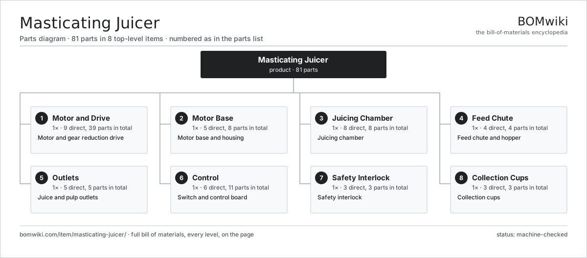
| # | Part | Qty | What it does |
|---|---|---|---|
| 1 | Motor and Drive 9 parts | 1× | Motor and gear reduction drive |
| 2 | Motor Base 5 parts | 1× | Motor base and housing |
| 3 | Juicing Chamber 8 parts | 1× | Juicing chamber |
| 4 | Feed Chute 4 parts | 1× | Feed chute and hopper |
| 5 | Outlets 5 parts | 1× | Juice and pulp outlets |
| 6 | Control 6 parts | 1× | Switch and control board |
| 7 | Safety Interlock 3 parts | 1× | Safety interlock |
| 8 | Collection Cups 3 parts | 1× | Collection cups |
3D model
No 3D model yet. Have a CAD file of this? Add a 3D model. STL renders right on this page; STEP, FreeCAD, and OpenSCAD sources are welcome too (openly licensed, like all 3D models on BOMwiki).
Build & assembly graph
expand / collapse · shared sub-assemblies converge · links to related products · est. labourTap an assembly to expand/collapse · tap a part to open it · use “Open page” for any node · drag to pan, scroll to zoom.
Bill of materials for Masticating Juicer
8 top-level lines · 61 rows shown · 81 parts total · indented to 3 levels| # | Item / sub-assembly | Part no. | Qty/assy | Ext. qty | Parts | Type |
|---|---|---|---|---|---|---|
| 1 | Motor and Drive 9 parts | masticating-juicer-drive | 1× | 1 | 39 | assembly |
| 1.1 | AC Induction Motor 6 parts | masticating-juicer-motor | 1× | 1 | 27 | assembly |
| 1.1.1 | Stator Assembly 3 parts + deeper › | stator-assembly | 1× | 1 | 3 | assembly |
| 1.1.2 | Rotor Assembly 4 parts + deeper › | rotor-assembly | 1× | 1 | 19 | assembly |
| 1.1.3 | Run Capacitor | masticating-juicer-run-cap | 1× | 1 | · | part |
| 1.1.4 | Thermal Cutout | masticating-juicer-thermal-cutout | 1× | 1 | · | part |
| 1.1.5 | Motor Fan | masticating-juicer-motor-fan | 1× | 1 | · | part |
| 1.1.6 | Ball Bearing | ball-bearing | 2× | 2 | · | part |
| 1.2 | Gearbox Housing | gearbox-housing | 1× | 1 | · | part |
| 1.3 | Worm and Worm Wheel | masticating-juicer-worm | 1× | 1 | · | part |
| 1.4 | Helical Gear Pair | gear-pair | 1× | 1 | · | part |
| 1.5 | Output Shaft | masticating-juicer-output-shaft | 1× | 1 | · | part |
| 1.6 | Drive Coupling | masticating-juicer-coupling | 1× | 1 | · | part |
| 1.7 | Ball Bearing | ball-bearing | 4× | 4 | · | part |
| 1.8 | Oil Seal | oil-seal | 2× | 2 | · | part |
| 1.9 | Fastener Set | fastener-set | 1× | 1 | · | part |
| 2 | Motor Base 5 parts | masticating-juicer-base | 1× | 1 | 8 | assembly |
| 2.1 | Base Housing | masticating-juicer-base-housing | 1× | 1 | · | part |
| 2.2 | Bottom Plate | masticating-juicer-base-plate | 1× | 1 | · | part |
| 2.3 | Mount Collar | masticating-juicer-mount-collar | 1× | 1 | · | part |
| 2.4 | Suction Foot | masticating-juicer-foot | 4× | 4 | · | part |
| 2.5 | Fastener Set | fastener-set | 1× | 1 | · | part |
| 3 | Juicing Chamber 8 parts | masticating-juicer-juicing | 1× | 1 | 8 | assembly |
| 3.1 | Juicing Bowl | masticating-juicer-bowl | 1× | 1 | · | part |
| 3.2 | Juicing Auger | masticating-juicer-auger | 1× | 1 | · | part |
| 3.3 | Fine Screen | masticating-juicer-fine-screen | 1× | 1 | · | part |
| 3.4 | Coarse Screen | masticating-juicer-coarse-screen | 1× | 1 | · | part |
| 3.5 | Blank Screen | masticating-juicer-blank-screen | 1× | 1 | · | part |
| 3.6 | Bowl Cap | masticating-juicer-bowl-cap | 1× | 1 | · | part |
| 3.7 | Wiper Blade | masticating-juicer-wiper | 1× | 1 | · | part |
| 3.8 | O-Ring Set | oring-set | 1× | 1 | · | part |
| 4 | Feed Chute 4 parts | masticating-juicer-feed | 1× | 1 | 4 | assembly |
| 4.1 | Feed Hopper | masticating-juicer-hopper | 1× | 1 | · | part |
| 4.2 | Feed Chute Neck | masticating-juicer-chute | 1× | 1 | · | part |
| 4.3 | Food Pusher | masticating-juicer-pusher | 1× | 1 | · | part |
| 4.4 | Anti-splash Flap | masticating-juicer-feed-flap | 1× | 1 | · | part |
| 5 | Outlets 5 parts | masticating-juicer-outlet | 1× | 1 | 5 | assembly |
| 5.1 | Juice Spout | masticating-juicer-juice-spout | 1× | 1 | · | part |
| 5.2 | Drip-stop Cap | masticating-juicer-spout-cap | 1× | 1 | · | part |
| 5.3 | Pulp Port | masticating-juicer-pulp-port | 1× | 1 | · | part |
| 5.4 | Pulp Pressure Knob | masticating-juicer-adjust-knob | 1× | 1 | · | part |
| 5.5 | O-Ring Set | oring-set | 1× | 1 | · | part |
| 6 | Control 6 parts | masticating-juicer-control | 1× | 1 | 11 | assembly |
| 6.1 | Rocker Switch | masticating-juicer-rocker-switch | 1× | 1 | · | part |
| 6.2 | Control Board 4 parts | masticating-juicer-control-board | 1× | 1 | 4 | assembly |
| 6.2.1 | Bare PCB | pcb-bare | 1× | 1 | · | part |
| 6.2.2 | Microcontroller | mcu | 1× | 1 | · | part |
| 6.2.3 | SMD Passive (R/C/L) | smd-passives | 1× | 1 | · | part |
| 6.2.4 | Current Shunt | masticating-juicer-current-shunt | 1× | 1 | · | part |
| 6.3 | Power Cord | masticating-juicer-power-cord | 1× | 1 | · | part |
| 6.4 | Relay | relay | 1× | 1 | · | part |
| 6.5 | Wire Bundle | wire-bundle | 1× | 1 | · | part |
| 6.6 | Connector | connector | 3× | 3 | · | part |
| 7 | Safety Interlock 3 parts | masticating-juicer-interlock | 1× | 1 | 3 | assembly |
| 7.1 | Interlock Switch | masticating-juicer-interlock-switch | 1× | 1 | · | part |
| 7.2 | Interlock Tab | masticating-juicer-interlock-tab | 1× | 1 | · | part |
| 7.3 | Coil Spring | coil-spring | 1× | 1 | · | part |
| 8 | Collection Cups 3 parts | masticating-juicer-cups | 1× | 1 | 3 | assembly |
| 8.1 | Juice Cup | masticating-juicer-juice-cup | 1× | 1 | · | part |
| 8.2 | Pulp Cup | masticating-juicer-pulp-cup | 1× | 1 | · | part |
| 8.3 | Cleaning Brush | masticating-juicer-cleaning-brush | 1× | 1 | · | part |
Related products
same domain, ranked by shared parts Chocolate Fondue Fountain
110 parts · shares 13 with this page
Chocolate Fondue Fountain
110 parts · shares 13 with this page
 Hand Mixer
114 parts · shares 13 with this page
Hand Mixer
114 parts · shares 13 with this page
 Compressor Ice Cream Maker
248 parts · shares 13 with this page
Personal Bullet Blender
144 parts · shares 13 with this page
Compressor Ice Cream Maker
248 parts · shares 13 with this page
Personal Bullet Blender
144 parts · shares 13 with this page
 Bread Machine
162 parts · shares 12 with this page
Bread Machine
162 parts · shares 12 with this page
Sourcing: possible vendors
Browse the supplier directory → Prices, MOQ, and lead times are algorithmic estimates, not quotes, and not claims about these companies. Company mappings are curated by keyword; est. price band $20–$600. How estimates work| Vendor | HQ | Specialty | MOQ | Lead time |
|---|---|---|---|---|
|
🇦🇺Breville
breville.com ↗
|
Sydney, AU | Kitchen appliances | 2,000 units | 6–10 wks |
| groupeseb.com ↗ | Écully, FR | Cookware & small appliances | 2,000 units | 6–10 wks |
| hamiltonbeach.com ↗ | Glen Allen, US | Small appliances | 2,000 units | 6–10 wks |
| panasonic.com ↗ | Osaka, JP | Electronics & appliances | 2,000 units | 6–10 wks |
|
🇨🇳Midea
midea.com ↗
|
Foshan, CN | Home appliances | 2,000 units | 6–10 wks |
1,039-word article