Desiccant Dehumidifier
ProductOverview
A desiccant dehumidifier removes moisture from air by adsorbing it onto a solid drying material rather than condensing it on a cold coil. Air passes through a slowly turning wheel coated with silica gel or zeolite, which grabs the water vapor; a separate heated airstream then bakes that water back out so the wheel can keep working. The advantage over a compressor dehumidifier is cold-weather performance: a refrigeration-based unit loses capacity and ices up below about 15 deg C, while a desiccant unit keeps pulling water down to near freezing, which suits cellars, garages, boats, and unheated rooms.
The machine runs two airstreams across one wheel. The Desiccant Wheel & Drive rotor is the core. The Process Air Path path dries the room, the Regeneration Air Path path re-dries the wheel, the Water Collection system captures the expelled moisture, a Control Board & Panel board sequences everything, and the Housing & Filters holds it all.
How desiccant drying works
The principle is adsorption: a porous solid with enormous internal surface area holds water molecules on its surface. The Desiccant Rotor (Silica Gel) is a honeycomb wheel impregnated with silica gel, presenting a very large area in a small package. The wheel is divided by Rotor Sector Seal partitions into two unequal sectors. Most of the wheel handles process air, where room air gives up its moisture to the dry desiccant. A smaller sector handles regeneration, where hot air drives the captured water back out. The wheel turns slowly, on the order of a few revolutions per hour, so each part of the media cycles between adsorbing and being dried.
Desiccant wheel and drive
The Desiccant Wheel & Drive assembly turns the rotor. A small synchronous Rotor Drive Motor drives the Rotor Hub & Shaft through a Rotor Drive Belt and a Helical Gear Pair reduction, holding the wheel to its slow set speed. The Rotor Sector Seal partitions are critical: they keep the hot regeneration air from leaking into the dried process air, which would undo the drying. If those seals wear, output falls even though the wheel and heater still work.
Process air path
The Process Air Path path is what dries the room. A Process Fan driven by a Process Fan Motor pulls room air in through the Process Inlet Plenum plenum and pushes it through the large sector of the wheel. The desiccant strips the moisture, and the air leaves through the Dry-Air Outlet Louver louver drier and a few degrees warmer, because adsorption releases heat. A Humidity Sensor at the inlet tells the control board the room's humidity so it knows when to run.
Regeneration air path
The Regeneration Air Path path re-dries the wheel so it can keep adsorbing. A Regeneration Fan driven by a Regeneration Fan Motor pulls a smaller airstream across a Heating Element that heats it to over 100 deg C, then forces it through the Regeneration Duct and the regeneration sector of the wheel. The heat drives the trapped water back out of the desiccant as vapor, refreshing that part of the media before it rotates back into the process stream. A Regeneration Thermostat holds the heater to a safe temperature and a Thermal Cutout opens the circuit if the airflow fails and the heater overheats.
Water collection
The hot, moisture-laden regeneration air must give up its water before it leaves. The Water Collection system runs that air across a Condenser Heat Exchanger cross-flow heat exchanger, often cooled by the incoming process air, so the water condenses and drips into a Water Tank. A Tank Float Switch switch stops the unit when the tank is full to prevent overflow. For unattended running, a Continuous Drain Port and Drain Hose let condensate run straight to a drain so the tank never needs emptying.
Control, housing, and power
The Control Board & Panel board acts as a humidistat. The Control Board carries an Microcontroller that compares measured humidity to the setpoint and runs the unit until the room reaches target. Three Relay outputs switch the rotor motor and the two fans, while an Solid-State Relay solid-state relay modulates the heater, which switches too often for a mechanical relay. The setpoint and tank status show on a Display & Buttons.
The Housing & Filters is a molded Front Panel and Rear Panel shell with a washable Intake Air Filter over the intake, a Carry Handle for carrying, and Rubber Foot pads underneath. Power enters through the Power & Wiring section: a Power Cord & Plug, a Strain Relief, and an internal Wire Bundle.
Use and trade-offs
Desiccant dehumidifiers trade energy for low-temperature ability. The regeneration heater makes them draw more power per litre of water than a compressor unit in warm conditions, so they make most sense where it is cold, where a refrigeration dehumidifier would simply ice over and stop. They are also lighter and quieter, with no compressor. The desiccant wheel lasts for years; the usual service items are the intake filter, the rotor seals, and the heater limit devices.
Desiccant Dehumidifier parts and their functions
7 top-level parts · 93 parts in total · full bill of materials below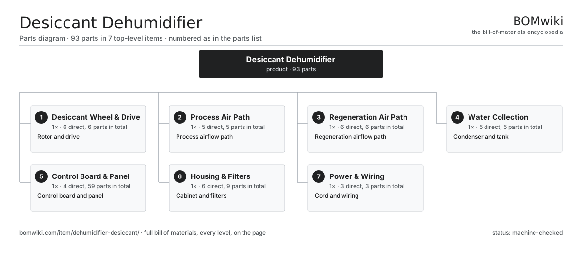
| # | Part | Qty | What it does |
|---|---|---|---|
| 1 | Desiccant Wheel & Drive 6 parts | 1× | Rotor and drive |
| 2 | Process Air Path 5 parts | 1× | Process airflow path |
| 3 | Regeneration Air Path 6 parts | 1× | Regeneration airflow path |
| 4 | Water Collection 5 parts | 1× | Condenser and tank |
| 5 | Control Board & Panel 4 parts | 1× | Control board and panel |
| 6 | Housing & Filters 6 parts | 1× | Cabinet and filters |
| 7 | Power & Wiring 3 parts | 1× | Cord and wiring |
3D model
No 3D model yet. Have a CAD file of this? Add a 3D model. STL renders right on this page; STEP, FreeCAD, and OpenSCAD sources are welcome too (openly licensed, like all 3D models on BOMwiki).
Build & assembly graph
expand / collapse · shared sub-assemblies converge · links to related products · est. labourTap an assembly to expand/collapse · tap a part to open it · use “Open page” for any node · drag to pan, scroll to zoom.
Bill of materials for Desiccant Dehumidifier
7 top-level lines · 46 rows shown · 93 parts total · indented to 3 levels| # | Item / sub-assembly | Part no. | Qty/assy | Ext. qty | Parts | Type |
|---|---|---|---|---|---|---|
| 1 | Desiccant Wheel & Drive 6 parts | dhd-desiccant-wheel | 1× | 1 | 6 | assembly |
| 1.1 | Desiccant Rotor (Silica Gel) | dhd-rotor-media | 1× | 1 | · | part |
| 1.2 | Rotor Hub & Shaft | dhd-rotor-hub | 1× | 1 | · | part |
| 1.3 | Rotor Drive Motor | dhd-rotor-motor | 1× | 1 | · | part |
| 1.4 | Rotor Drive Belt | dhd-drive-belt | 1× | 1 | · | part |
| 1.5 | Rotor Sector Seal | dhd-rotor-seal | 1× | 1 | · | part |
| 1.6 | Helical Gear Pair | gear-pair | 1× | 1 | · | part |
| 2 | Process Air Path 5 parts | dhd-process-air | 1× | 1 | 5 | assembly |
| 2.1 | Process Fan | dhd-process-fan | 1× | 1 | · | part |
| 2.2 | Process Fan Motor | dhd-process-motor | 1× | 1 | · | part |
| 2.3 | Process Inlet Plenum | dhd-process-inlet | 1× | 1 | · | part |
| 2.4 | Dry-Air Outlet Louver | dhd-process-outlet | 1× | 1 | · | part |
| 2.5 | Humidity Sensor | dhd-humidity-sensor | 1× | 1 | · | part |
| 3 | Regeneration Air Path 6 parts | dhd-regen-air | 1× | 1 | 6 | assembly |
| 3.1 | Heating Element | heating-element | 1× | 1 | · | part |
| 3.2 | Regeneration Fan | dhd-regen-fan | 1× | 1 | · | part |
| 3.3 | Regeneration Fan Motor | dhd-regen-motor | 1× | 1 | · | part |
| 3.4 | Regeneration Duct | dhd-regen-duct | 1× | 1 | · | part |
| 3.5 | Regeneration Thermostat | dhd-regen-thermostat | 1× | 1 | · | part |
| 3.6 | Thermal Cutout | dhd-thermal-cutout | 1× | 1 | · | part |
| 4 | Water Collection 5 parts | dhd-water-collection | 1× | 1 | 5 | assembly |
| 4.1 | Condenser Heat Exchanger | dhd-condenser | 1× | 1 | · | part |
| 4.2 | Water Tank | dhd-water-tank | 1× | 1 | · | part |
| 4.3 | Tank Float Switch | dhd-tank-float | 1× | 1 | · | part |
| 4.4 | Continuous Drain Port | dhd-drain-port | 1× | 1 | · | part |
| 4.5 | Drain Hose | dhd-drain-hose | 1× | 1 | · | part |
| 5 | Control Board & Panel 4 parts | dhd-control | 1× | 1 | 59 | assembly |
| 5.1 | Control Board 4 parts | dhd-control-board | 1× | 1 | 54 | assembly |
| 5.1.1 | Bare PCB | pcb-bare | 1× | 1 | · | part |
| 5.1.2 | Microcontroller | mcu | 1× | 1 | · | part |
| 5.1.3 | SMD Passive (R/C/L) | smd-passives | 45× | 45 | · | part |
| 5.1.4 | Connector | connector | 7× | 7 | · | part |
| 5.2 | Display & Buttons | dhd-display | 1× | 1 | · | part |
| 5.3 | Relay | relay | 3× | 3 | · | part |
| 5.4 | Solid-State Relay | dhd-ssr | 1× | 1 | · | part |
| 6 | Housing & Filters 6 parts | dhd-housing | 1× | 1 | 9 | assembly |
| 6.1 | Front Panel | dhd-cabinet-front | 1× | 1 | · | part |
| 6.2 | Rear Panel | dhd-cabinet-rear | 1× | 1 | · | part |
| 6.3 | Intake Air Filter | dhd-air-filter | 1× | 1 | · | part |
| 6.4 | Carry Handle | dhd-handle | 1× | 1 | · | part |
| 6.5 | Rubber Foot | dhd-foot | 4× | 4 | · | part |
| 6.6 | Fastener Set | fastener-set | 1× | 1 | · | part |
| 7 | Power & Wiring 3 parts | dhd-power | 1× | 1 | 3 | assembly |
| 7.1 | Power Cord & Plug | dhd-power-cord | 1× | 1 | · | part |
| 7.2 | Wire Bundle | wire-bundle | 1× | 1 | · | part |
| 7.3 | Strain Relief | dhd-strain-relief | 1× | 1 | · | part |
Related products
same domain, ranked by shared parts Downdraft Cooktop
50 parts · shares 2 with this page
Downdraft Cooktop
50 parts · shares 2 with this page
 Bladeless Fan
64 parts · shares 2 with this page
Bladeless Fan
64 parts · shares 2 with this page
 Misting Fan
116 parts · shares 2 with this page
Misting Fan
116 parts · shares 2 with this page
 Portable Washing Machine
167 parts · shares 2 with this page
Portable Washing Machine
167 parts · shares 2 with this page
 Stand Fan
70 parts · shares 2 with this page
Stand Fan
70 parts · shares 2 with this page
 Top-Load Washing Machine
214 parts · shares 2 with this page
Top-Load Washing Machine
214 parts · shares 2 with this page
Sourcing: possible vendors
Browse the supplier directory → Prices, MOQ, and lead times are algorithmic estimates, not quotes, and not claims about these companies. Company mappings are curated by keyword; est. price band $150–$3k. How estimates work| Vendor | HQ | Specialty | MOQ | Lead time |
|---|---|---|---|---|
| whirlpoolcorp.com ↗ | Benton Harbor, US | Home appliances | 1,000 units | 8–14 wks |
| bsh-group.com ↗ | Munich, DE | Appliances (Bosch, Siemens) | 1,000 units | 8–14 wks |
| electroluxgroup.com ↗ | Stockholm, SE | Home appliances | 1,000 units | 8–14 wks |
| lg.com ↗ | Seoul, KR | Appliances & electronics | 1,000 units | 8–14 wks |
|
🇨🇳Haier
haier.com ↗
|
Qingdao, CN | Home appliances | 1,000 units | 8–14 wks |
848-word article