Stand Fan
ProductOverview
A stand fan, also called a pedestal fan, is a free-standing floor fan whose head sits on top of a tall adjustable column. It is the larger relative of the table fan: the same kind of motor and blade, raised to chest or head height so the airflow reaches a seated or standing person across a room. The typical unit carries a 400 mm three-blade impeller driven by a shaded-pole motor, swings the head from side to side to spread the air, and stands between one metre and one and a third metres tall.
The machine breaks into a Motor Assembly that spins the blade, a Blade Assembly that moves the air behind its safety guard, an Oscillation Assembly that swings the head, a Stand Assembly that holds everything up, and a Control Assembly for speed and timing. A Wire Bundle carries mains power from the lead through the column to the head, and a Fastener Set holds the parts together. The design is cheap to build, easy to repair, and has changed little in decades because it works.
How it works
Power reaches the Motor Assembly, where a Stator Assembly energised through the Motor Winding sets up a rotating field that drags the Rotor Assembly around with it. A shaded-pole motor needs no starting capacitor for the basic action: a copper shading ring on part of each pole delays the field there and gives the rotor a definite direction to turn. The Motor Shaft runs through the Motor Housing on a Ball Bearing at the front and an oil-impregnated Sleeve Bearing at the rear. If the winding ever overheats, a Thermal Fuse in series with it opens and protects the motor from burning out.
The front of the shaft carries a thread for the Fan Blade, a three-blade polypropylene impeller of 400 mm sweep moulded with a set pitch. At about 1300 RPM on high speed it moves 60 to 75 cubic metres of air per minute. A Spinner Nut with a reverse thread holds the blade on, so the running torque tightens it rather than spinning it loose. A Front Guard and Rear Guard in chromed steel wire cage the blade, joined at the rim by a ring of Guard Clip springs, with gaps small enough to keep fingers clear of the moving blade.
Oscillation
The side-to-side swing comes from the Oscillation Assembly mounted on the back of the motor. The rear of the Motor Shaft is cut as a worm that drives a Helical Gear Pair inside a Gearbox Housing, stepping the high motor speed down to a slow turn of a few revolutions per minute. That slow output turns a Crank Arm, and a Link Rod from the crank to a fixed point on the column converts the rotation into a back-and-forth sweep of the whole head, usually about 80 degrees. The user can stop the swing with the Oscillation Knob, a pull knob on top of the gearbox that slides a Clutch Dog in and out of mesh. Pulled up, the head stays fixed; pushed down, it oscillates. Because the gearbox is geared so far down, it draws very little extra power and runs for years on a charge of grease.
Stand and adjustment
The Stand Assembly gives the fan its height and stability. A weighted Base of around 4 kg, usually a cross or disc, keeps the fan from tipping when the head is turned out to one side. A Lower Stand Tube rises from the base, and a Upper Stand Tube slides inside it to set the working height anywhere from 1.0 to 1.3 m. A threaded Height Collar clamps the inner tube at the chosen height. At the top, a Head Pivot lets the head tilt up or down, locked by a Tilt Knob, so the user can aim the airflow at the floor for a child or up over a bed.
Controls and electronics
Speed is set at the Control Assembly in the back of the head. The simplest control is a Speed Switch, a bank of push buttons that select different taps on the Motor Winding: more turns in circuit means a weaker field and a slower blade. A Run Capacitor of about 1.5 microfarad trims the motor phase and helps it run smoothly. Better models add a Control Board carrying an Microcontroller with a sleep timer, a triac for stepless speed, a small Power Supply for the logic, and a receiver for a Remote Handset handset. The handset is a small battery unit with a Remote Keypad in silicone inside a Remote Shell of ABS, sending speed and timer commands so the user need not walk to the fan.
Use and care
A stand fan suits a bedroom, office or workshop where a person needs moving air at body height rather than the ceiling-down draught of a ceiling fan. It uses 50 to 60 watts on high, a fraction of an air conditioner, and cools by evaporation off the skin rather than by lowering room temperature, so it is only worth running when someone is in the room. Care is light: wipe dust off the Fan Blade and guards, since a coat of dust unbalances the blade and makes the fan wobble and hum, and add a drop of oil to the rear Sleeve Bearing if the motor starts to whine after several seasons. The blade, guard and remote are the parts most often replaced, all of them simple to swap without tools beyond a screwdriver.
Stand Fan parts and their functions
7 top-level parts · 70 parts in total · full bill of materials below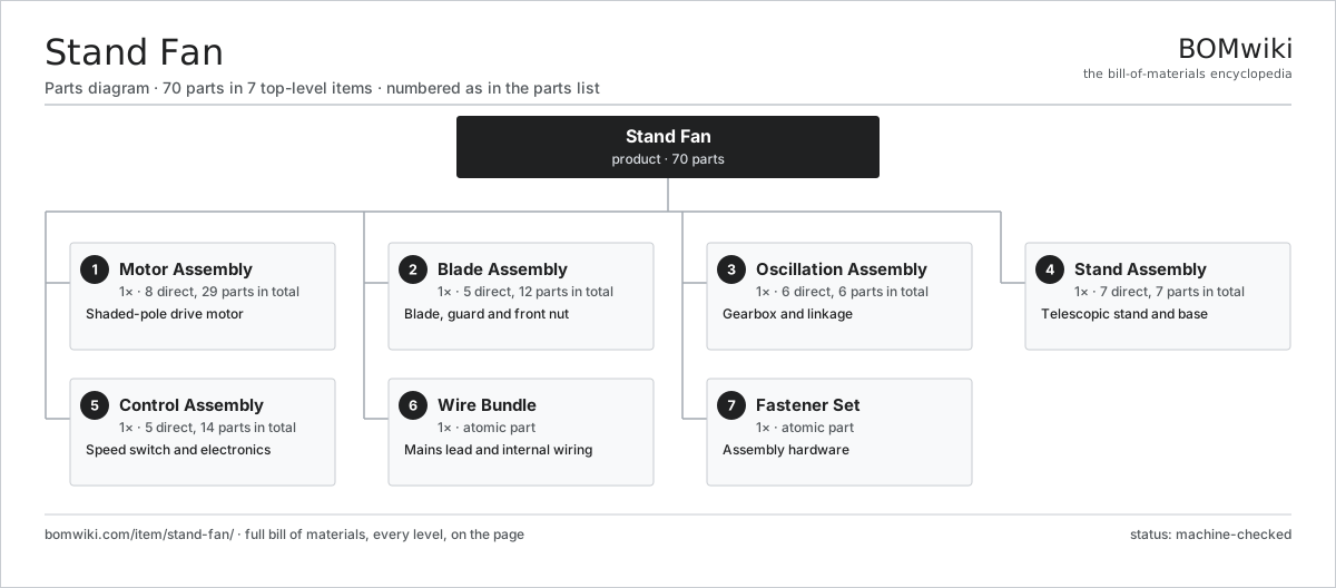
| # | Part | Qty | What it does |
|---|---|---|---|
| 1 | Motor Assembly 8 parts | 1× | Shaded-pole drive motor |
| 2 | Blade Assembly 5 parts | 1× | Blade, guard and front nut |
| 3 | Oscillation Assembly 6 parts | 1× | Gearbox and linkage |
| 4 | Stand Assembly 7 parts | 1× | Telescopic stand and base |
| 5 | Control Assembly 5 parts | 1× | Speed switch and electronics |
| 6 | Wire Bundle | 1× | Mains lead and internal wiring |
| 7 | Fastener Set | 1× | Assembly hardware |
3D model
No 3D model yet. Have a CAD file of this? Add a 3D model. STL renders right on this page; STEP, FreeCAD, and OpenSCAD sources are welcome too (openly licensed, like all 3D models on BOMwiki).
Build & assembly graph
expand / collapse · shared sub-assemblies converge · links to related products · est. labourTap an assembly to expand/collapse · tap a part to open it · use “Open page” for any node · drag to pan, scroll to zoom.
Bill of materials for Stand Fan
7 top-level lines · 53 rows shown · 70 parts total · indented to 3 levels| # | Item / sub-assembly | Part no. | Qty/assy | Ext. qty | Parts | Type |
|---|---|---|---|---|---|---|
| 1 | Motor Assembly 8 parts | stand-fan-motor-assembly | 1× | 1 | 29 | assembly |
| 1.1 | Stator Assembly 3 parts | stator-assembly | 1× | 1 | 3 | assembly |
| 1.1.1 | Stator Core (laminations) | stator-core | 1× | 1 | · | part |
| 1.1.2 | Copper Winding | copper-winding | 1× | 1 | · | part |
| 1.1.3 | Slot Insulation | stator-insulation | 1× | 1 | · | part |
| 1.2 | Motor Winding | stand-fan-motor-winding | 2× | 2 | · | part |
| 1.3 | Rotor Assembly 4 parts | rotor-assembly | 1× | 1 | 19 | assembly |
| 1.3.1 | Rotor Shaft | rotor-shaft | 1× | 1 | · | part |
| 1.3.2 | Rotor Core | rotor-core | 1× | 1 | · | part |
| 1.3.3 | Neodymium Magnet | neodymium-magnet | 16× | 16 | · | part |
| 1.3.4 | Ball Bearing | ball-bearing | 1× | 1 | · | part |
| 1.4 | Motor Shaft | stand-fan-motor-shaft | 1× | 1 | · | part |
| 1.5 | Motor Housing | stand-fan-motor-housing | 1× | 1 | · | part |
| 1.6 | Thermal Fuse | stand-fan-thermal-fuse | 1× | 1 | · | part |
| 1.7 | Ball Bearing | ball-bearing | 1× | 1 | · | part |
| 1.8 | Sleeve Bearing | stand-fan-sleeve-bearing | 1× | 1 | · | part |
| 2 | Blade Assembly 5 parts | stand-fan-blade-assembly | 1× | 1 | 12 | assembly |
| 2.1 | Fan Blade | stand-fan-blade | 1× | 1 | · | part |
| 2.2 | Front Guard | stand-fan-front-guard | 1× | 1 | · | part |
| 2.3 | Rear Guard | stand-fan-rear-guard | 1× | 1 | · | part |
| 2.4 | Spinner Nut | stand-fan-spinner-nut | 1× | 1 | · | part |
| 2.5 | Guard Clip | stand-fan-guard-clip | 8× | 8 | · | part |
| 3 | Oscillation Assembly 6 parts | stand-fan-oscillation-assembly | 1× | 1 | 6 | assembly |
| 3.1 | Gearbox Housing | gearbox-housing | 1× | 1 | · | part |
| 3.2 | Helical Gear Pair | gear-pair | 1× | 1 | · | part |
| 3.3 | Crank Arm | stand-fan-crank-arm | 1× | 1 | · | part |
| 3.4 | Link Rod | stand-fan-link-rod | 1× | 1 | · | part |
| 3.5 | Oscillation Knob | stand-fan-osc-knob | 1× | 1 | · | part |
| 3.6 | Clutch Dog | stand-fan-clutch-dog | 1× | 1 | · | part |
| 4 | Stand Assembly 7 parts | stand-fan-stand-assembly | 1× | 1 | 7 | assembly |
| 4.1 | Base | stand-fan-base | 1× | 1 | · | part |
| 4.2 | Lower Stand Tube | stand-fan-lower-tube | 1× | 1 | · | part |
| 4.3 | Upper Stand Tube | stand-fan-upper-tube | 1× | 1 | · | part |
| 4.4 | Height Collar | stand-fan-height-collar | 1× | 1 | · | part |
| 4.5 | Head Pivot | stand-fan-head-pivot | 1× | 1 | · | part |
| 4.6 | Tilt Knob | stand-fan-tilt-knob | 1× | 1 | · | part |
| 4.7 | Fastener Set | fastener-set | 1× | 1 | · | part |
| 5 | Control Assembly 5 parts | stand-fan-control-assembly | 1× | 1 | 14 | assembly |
| 5.1 | Speed Switch | stand-fan-speed-switch | 1× | 1 | · | part |
| 5.2 | Run Capacitor | stand-fan-run-capacitor | 1× | 1 | · | part |
| 5.3 | Control Board 5 parts | stand-fan-control-board | 1× | 1 | 6 | assembly |
| 5.3.1 | Bare PCB | pcb-bare | 1× | 1 | · | part |
| 5.3.2 | Microcontroller | mcu | 1× | 1 | · | part |
| 5.3.3 | SMD Passive (R/C/L) | smd-passives | 1× | 1 | · | part |
| 5.3.4 | Power Supply | power-supply | 1× | 1 | · | part |
| 5.3.5 | Connector | connector | 2× | 2 | · | part |
| 5.4 | Remote Handset 3 parts | stand-fan-remote | 1× | 1 | 3 | assembly |
| 5.4.1 | Bare PCB | pcb-bare | 1× | 1 | · | part |
| 5.4.2 | Remote Keypad | stand-fan-remote-keypad | 1× | 1 | · | part |
| 5.4.3 | Remote Shell | stand-fan-remote-shell | 1× | 1 | · | part |
| 5.5 | Connector | connector | 3× | 3 | · | part |
| 6 | Wire Bundle | wire-bundle | 1× | 1 | · | part |
| 7 | Fastener Set | fastener-set | 1× | 1 | · | part |
Related products
same domain, ranked by shared parts Trash Compactor
85 parts · shares 11 with this page
Trash Compactor
85 parts · shares 11 with this page
 Bladeless Fan
64 parts · shares 12 with this page
Bladeless Fan
64 parts · shares 12 with this page
 Misting Fan
116 parts · shares 11 with this page
Misting Fan
116 parts · shares 11 with this page
 Portable Washing Machine
167 parts · shares 11 with this page
Portable Washing Machine
167 parts · shares 11 with this page
 Top-Load Washing Machine
214 parts · shares 11 with this page
Gas Clothes Dryer
99 parts · shares 11 with this page
Top-Load Washing Machine
214 parts · shares 11 with this page
Gas Clothes Dryer
99 parts · shares 11 with this page
Sourcing: possible vendors
Browse the supplier directory → Prices, MOQ, and lead times are algorithmic estimates, not quotes, and not claims about these companies. Company mappings are curated by keyword; est. price band $150–$3k. How estimates work| Vendor | HQ | Specialty | MOQ | Lead time |
|---|---|---|---|---|
| whirlpoolcorp.com ↗ | Benton Harbor, US | Home appliances | 1,000 units | 8–14 wks |
| bsh-group.com ↗ | Munich, DE | Appliances (Bosch, Siemens) | 1,000 units | 8–14 wks |
| electroluxgroup.com ↗ | Stockholm, SE | Home appliances | 1,000 units | 8–14 wks |
| lg.com ↗ | Seoul, KR | Appliances & electronics | 1,000 units | 8–14 wks |
|
🇨🇳Haier
haier.com ↗
|
Qingdao, CN | Home appliances | 1,000 units | 8–14 wks |
1,004-word article