Front-Load Washing Machine
ProductOverview
A front-load washing machine cleans clothes by tumbling them in a horizontal drum that is only partly filled with water, lifting the load on paddles and dropping it back into a shallow wash bath over and over. This tumbling action does the mechanical work that a vertical agitator would do in a top-loader, but it uses far less water and is gentler on fabric, which is why front-loaders dominate where water and energy cost more. The whole machine is a spinning mass of wet laundry suspended inside a fixed cabinet, so most of its engineering goes to managing vibration and sealing water in.
The structure is the Cabinet & Counterweights, a Cabinet Wrapper wrapper closed by a Top Panel and a Rear Service Panel for service access, standing on four adjustable Leveling Foot feet. Bolted to it are heavy Front Concrete Counterweight and Top Concrete Counterweight concrete blocks. These counterweights are not dead weight by accident: they raise the inertia of the suspended tub assembly so it resists the off-balance forces a wet load throws off at spin speed, keeping the machine from walking across the floor.
Drum and tub
The laundry lives in the Drum System. A perforated Stainless Inner Drum of SUS430 stainless holds the clothes and lets water and detergent flow through its holes. It is bolted to an aluminum Drum Spider hub on the Drum Shaft, and the whole rotating assembly turns inside a sealed Outer Tub of glass-filled polypropylene that holds the wash water. Two Drum Bearing bearings carry the shaft and an Oil Seal keeps wash water out of them, the single most common wear-out point on a front-loader because the seal eventually lets water reach the bearings. Three Drum Lifter paddles inside the drum scoop the load up the rising side so it tumbles back down rather than sliding.
Drive
Rotation comes from the Drive System. A Drive Motor (BLDC) BLDC motor spins a small Motor Pulley connected by a poly-V Drive Belt to the large Drum Pulley on the drum shaft, a reduction that gives the torque needed to tumble a heavy load and the speed needed to spin it dry. A Tachometer Sensor reports drum speed back to the control so it can hold a slow wash tumble or ramp to a 1400 rpm spin precisely. Some machines replace this with a direct-drive motor on the shaft and drop the belt entirely; the belt-drive layout shown here is the most common and the easiest to service.
Suspension
Because the drum runs off-balance whenever clothes clump on one side, the Suspension isolates it from the cabinet. Two Suspension Spring springs hang the tub from the top of the cabinet, and two Friction Shock Damper friction dampers below absorb the energy of its swing, working like the spring-and-damper at a car wheel. Snubber Pad friction pads add damping at the spring seats. During the spin ramp the control deliberately pauses to redistribute a badly balanced load before committing to high speed, because the suspension can only absorb so much imbalance.
Water, heat, and door
The Water System manages every drop. Two Inlet Valve solenoids admit hot and cold water through the Fill Hose, a Flow Meter counts the volume, and the Pressure Switch confirms the level by reading the water column in a trap tube. The internal Heating Element raises wash temperature to as high as 90 °C for heavy soils, watched by the Water Temperature Sensor. A Recirculation Pump sprays wash liquor back over the load to wet it faster, and at the end the Drain Pump empties the tub through the Drain Hose. The Door System seals the front: a bowl-shaped Door Glass in a Door Frame presses against an EPDM Door Boot Seal bellows that bridges the gap between the fixed tub and the cabinet opening. A Door Interlock interlock keeps the door shut whenever the drum is moving or water is present.
Dispenser and control
Detergent enters through the Detergent Dispenser, a pull-out Dispenser Drawer with separate compartments for prewash, main wash, and softener. At the right moment in the cycle a dedicated Inlet Valve flushes water through the matching compartment, and a Siphon Cap siphons the softener out all at once so it is not washed away early. The whole sequence is run by the Control System system. A Main Control Board with its Microcontroller times the cycle and switches the heater, valves, and pumps, while a separate Motor Inverter Board drives the BLDC motor through an IGBT Power Module for smooth variable speed. A UI Board reads the user's choices from a Program Selector Encoder program dial and Capacitive Touch Key keys and shows progress on the LCD Panel.
Variants and use
Front-loaders scale from compact 7 kg machines up to 12 kg family units, with spin speeds from 1000 to 1600 rpm. Higher trims add steam generators for sanitizing and wrinkle reduction, automatic detergent dosing tanks, and load-weight sensing that trims water and time to the actual load. Washer-dryer combination units add a condenser and a second heater to dry in the same drum. The mechanical core stays constant across all of them: a perforated drum inside a sealed tub, a counterweighted suspended mass, a motor and belt or direct drive, and a sequencing control that meters water, heat, and spin.
Front-Load Washing Machine parts and their functions
9 top-level parts · 370 parts in total · full bill of materials below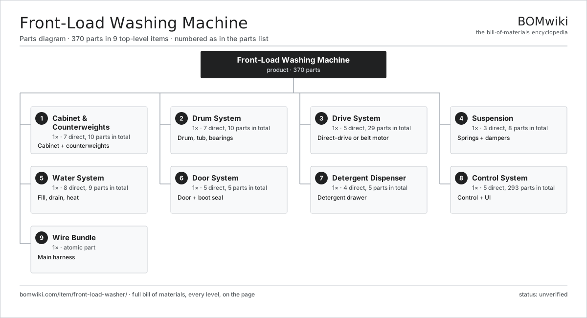
| # | Part | Qty | What it does |
|---|---|---|---|
| 1 | Cabinet & Counterweights 7 parts | 1× | Cabinet + counterweights |
| 2 | Drum System 7 parts | 1× | Drum, tub, bearings |
| 3 | Drive System 5 parts | 1× | Direct-drive or belt motor |
| 4 | Suspension 3 parts | 1× | Springs + dampers |
| 5 | Water System 8 parts | 1× | Fill, drain, heat |
| 6 | Door System 5 parts | 1× | Door + boot seal |
| 7 | Detergent Dispenser 4 parts | 1× | Detergent drawer |
| 8 | Control System 5 parts | 1× | Control + UI |
| 9 | Wire Bundle | 1× | Main harness |
3D model
No 3D model yet. Have a CAD file of this? Add a 3D model. STL renders right on this page; STEP, FreeCAD, and OpenSCAD sources are welcome too (openly licensed, like all 3D models on BOMwiki).
Build & assembly graph
expand / collapse · shared sub-assemblies converge · links to related products · est. labourTap an assembly to expand/collapse · tap a part to open it · use “Open page” for any node · drag to pan, scroll to zoom.
Bill of materials for Front-Load Washing Machine
9 top-level lines · 74 rows shown · 370 parts total · indented to 3 levels| # | Item / sub-assembly | Part no. | Qty/assy | Ext. qty | Parts | Type |
|---|---|---|---|---|---|---|
| 1 | Cabinet & Counterweights 7 parts | flw-cabinet | 1× | 1 | 10 | assembly |
| 1.1 | Cabinet Wrapper | flw-cabinet-wrap | 1× | 1 | · | part |
| 1.2 | Top Panel | flw-top-panel | 1× | 1 | · | part |
| 1.3 | Rear Service Panel | flw-rear-panel | 1× | 1 | · | part |
| 1.4 | Front Concrete Counterweight | flw-front-counterweight | 1× | 1 | · | part |
| 1.5 | Top Concrete Counterweight | flw-top-counterweight | 1× | 1 | · | part |
| 1.6 | Leveling Foot | flw-leveling-foot | 4× | 4 | · | part |
| 1.7 | Fastener Set | fastener-set | 1× | 1 | · | part |
| 2 | Drum System 7 parts | flw-drum-system | 1× | 1 | 10 | assembly |
| 2.1 | Stainless Inner Drum | flw-inner-drum | 1× | 1 | · | part |
| 2.2 | Outer Tub | flw-outer-tub | 1× | 1 | · | part |
| 2.3 | Drum Spider | flw-spider | 1× | 1 | · | part |
| 2.4 | Drum Shaft | flw-drum-shaft | 1× | 1 | · | part |
| 2.5 | Drum Bearing | drum-bearing | 2× | 2 | · | part |
| 2.6 | Oil Seal | oil-seal | 1× | 1 | · | part |
| 2.7 | Drum Lifter | flw-lifter | 3× | 3 | · | part |
| 3 | Drive System 5 parts | flw-drive-system | 1× | 1 | 29 | assembly |
| 3.1 | Drive Motor (BLDC) 4 parts | flw-drive-motor | 1× | 1 | 25 | assembly |
| 3.1.1 | Stator Assembly 3 parts + deeper › | stator-assembly | 1× | 1 | 3 | assembly |
| 3.1.2 | Rotor Assembly 4 parts + deeper › | rotor-assembly | 1× | 1 | 19 | assembly |
| 3.1.3 | Motor Housing | motor-housing | 1× | 1 | · | part |
| 3.1.4 | Ball Bearing | ball-bearing | 2× | 2 | · | part |
| 3.2 | Motor Pulley | flw-motor-pulley | 1× | 1 | · | part |
| 3.3 | Drum Pulley | flw-drum-pulley | 1× | 1 | · | part |
| 3.4 | Drive Belt | drive-belt | 1× | 1 | · | part |
| 3.5 | Tachometer Sensor | flw-tach-sensor | 1× | 1 | · | part |
| 4 | Suspension 3 parts | flw-suspension | 1× | 1 | 8 | assembly |
| 4.1 | Suspension Spring | flw-suspension-spring | 2× | 2 | · | part |
| 4.2 | Friction Shock Damper | flw-shock-damper | 2× | 2 | · | part |
| 4.3 | Snubber Pad | flw-snubber-pad | 4× | 4 | · | part |
| 5 | Water System 8 parts | flw-water-system | 1× | 1 | 9 | assembly |
| 5.1 | Inlet Valve | inlet-valve | 2× | 2 | · | part |
| 5.2 | Fill Hose | flw-fill-hose | 1× | 1 | · | part |
| 5.3 | Drain Pump | drain-pump | 1× | 1 | · | part |
| 5.4 | Drain Hose | flw-drain-hose | 1× | 1 | · | part |
| 5.5 | Recirculation Pump | flw-recirc-pump | 1× | 1 | · | part |
| 5.6 | Heating Element | heating-element | 1× | 1 | · | part |
| 5.7 | Pressure Switch | pressure-switch | 1× | 1 | · | part |
| 5.8 | Flow Meter | flw-flow-meter | 1× | 1 | · | part |
| 6 | Door System 5 parts | flw-door-system | 1× | 1 | 5 | assembly |
| 6.1 | Door Frame | flw-door-frame | 1× | 1 | · | part |
| 6.2 | Door Glass | flw-door-glass | 1× | 1 | · | part |
| 6.3 | Door Hinge | flw-door-hinge | 1× | 1 | · | part |
| 6.4 | Door Interlock | flw-door-lock | 1× | 1 | · | part |
| 6.5 | Door Boot Seal | flw-boot-seal | 1× | 1 | · | part |
| 7 | Detergent Dispenser 4 parts | flw-dispenser | 1× | 1 | 5 | assembly |
| 7.1 | Dispenser Drawer | flw-dispenser-drawer | 1× | 1 | · | part |
| 7.2 | Dispenser Housing | flw-dispenser-housing | 1× | 1 | · | part |
| 7.3 | Siphon Cap | flw-siphon-cap | 2× | 2 | · | part |
| 7.4 | Inlet Valve | inlet-valve | 1× | 1 | · | part |
| 8 | Control System 5 parts | flw-control | 1× | 1 | 293 | assembly |
| 8.1 | Main Control Board 6 parts | flw-main-board | 1× | 1 | 162 | assembly |
| 8.1.1 | Bare PCB | pcb-bare | 1× | 1 | · | part |
| 8.1.2 | Microcontroller | mcu | 1× | 1 | · | part |
| 8.1.3 | Relay | relay | 6× | 6 | · | part |
| 8.1.4 | Triac | triac | 2× | 2 | · | part |
| 8.1.5 | Connector | connector | 12× | 12 | · | part |
| 8.1.6 | SMD Passive (R/C/L) | smd-passives | 140× | 140 | · | part |
| 8.2 | Motor Inverter Board 6 parts | flw-motor-inverter | 1× | 1 | 88 | assembly |
| 8.2.1 | Bare PCB | pcb-bare | 1× | 1 | · | part |
| 8.2.2 | Microcontroller | mcu | 1× | 1 | · | part |
| 8.2.3 | IGBT Power Module | igbt-module | 1× | 1 | · | part |
| 8.2.4 | Gate Driver IC | gate-driver-ic | 3× | 3 | · | part |
| 8.2.5 | DC-Link Capacitor | dc-link-cap | 2× | 2 | · | part |
| 8.2.6 | SMD Passive (R/C/L) | smd-passives | 80× | 80 | · | part |
| 8.3 | UI Board 5 parts | flw-ui-board | 1× | 1 | 41 | assembly |
| 8.3.1 | Bare PCB | pcb-bare | 1× | 1 | · | part |
| 8.3.2 | Microcontroller | mcu | 1× | 1 | · | part |
| 8.3.3 | Program Selector Encoder | flw-rotary-encoder | 1× | 1 | · | part |
| 8.3.4 | Capacitive Touch Key | flw-touch-key | 8× | 8 | · | part |
| 8.3.5 | SMD Passive (R/C/L) | smd-passives | 30× | 30 | · | part |
| 8.4 | LCD Panel | lcd-panel | 1× | 1 | · | part |
| 8.5 | Water Temperature Sensor | flw-temp-sensor | 1× | 1 | · | part |
| 9 | Wire Bundle | wire-bundle | 1× | 1 | · | part |
Related products
same domain, ranked by shared parts Washing Machine
185 parts · shares 19 with this page
Washing Machine
185 parts · shares 19 with this page
 Top-Load Washing Machine
214 parts · shares 17 with this page
Top-Load Washing Machine
214 parts · shares 17 with this page
 Dishwasher
146 parts · shares 16 with this page
Portable Dishwasher
253 parts · shares 16 with this page
Dishwasher
146 parts · shares 16 with this page
Portable Dishwasher
253 parts · shares 16 with this page
 Clothes Dryer
240 parts · shares 14 with this page
Clothes Dryer
240 parts · shares 14 with this page
 Air Conditioner
117 parts · shares 12 with this page
Air Conditioner
117 parts · shares 12 with this page
Sourcing: possible vendors
Browse the supplier directory → Prices, MOQ, and lead times are algorithmic estimates, not quotes, and not claims about these companies. Company mappings are curated by keyword; est. price band $150–$3k. How estimates work| Vendor | HQ | Specialty | MOQ | Lead time |
|---|---|---|---|---|
| whirlpoolcorp.com ↗ | Benton Harbor, US | Home appliances | 1,000 units | 8–14 wks |
| bsh-group.com ↗ | Munich, DE | Appliances (Bosch, Siemens) | 1,000 units | 8–14 wks |
| electroluxgroup.com ↗ | Stockholm, SE | Home appliances | 1,000 units | 8–14 wks |
| lg.com ↗ | Seoul, KR | Appliances & electronics | 1,000 units | 8–14 wks |
|
🇨🇳Haier
haier.com ↗
|
Qingdao, CN | Home appliances | 1,000 units | 8–14 wks |
928-word article