Misting Fan
ProductOverview
A misting fan combines an ordinary pedestal fan with a high-pressure water system so the moving air carries a cloud of fine droplets. The droplets evaporate as they travel, pulling heat out of the surrounding air and dropping the perceived temperature by several degrees. Because the cooling depends on evaporation, the unit works best outdoors in dry, hot conditions: on a patio, at a market stall, or beside a worksite where conventional air conditioning is impractical.
The machine splits into two cooperating systems. The Fan Head Assembly moves the air the way any fan does, while the Misting System atomizes water into a ring of mist in front of the grille. A Water Supply feeds the pump, an Oscillation Mechanism mechanism sweeps the head across the area, and a Column & Base holds everything at standing height. A Control Board board ties the fan speed and mist together.
Fan head and airflow
The Fan Head Assembly is built around a single-phase Fan Motor, usually a permanent-split-capacitor or shaded-pole AC motor running on Stator Assembly and Rotor Assembly windings inside an Motor Housing. The shaft turns on two Ball Bearing supports and drives a three-blade Fan Blade (3-Blade) held by a Blade Retaining Cap. Pitched polypropylene blades pull a high-volume, low-pressure stream of air, which is what the mist needs to travel any distance.
A front and rear Front Grille and Rear Grille guard the blade and give the Nozzle Ring a place to mount. A Run Capacitor phase-shifts the start winding so the motor self-starts, and a Thermal Fuse opens the circuit if the motor overheats from a stalled blade or blocked airflow.
Misting system
The Misting System is what separates this product from a plain fan. A Misting Pump, a small diaphragm pump driven by a Pump Motor, draws water through a Inlet Filter Screen and raises it to roughly 70 psi. The Pump Diaphragm flexes against a set of Pump Check Valves to move water in pulses, and a Pressure Relief Valve valve bleeds off excess pressure so the pump does not stall.
Pressurized water travels up the High-Pressure Supply Tube to the Nozzle Ring, where eight Misting Nozzle orifices break it into 20-50 micron droplets. At that size the water flashes to vapor almost instantly in dry air, so it cools the air without wetting people standing nearby. Brass or stainless nozzles resist the mineral scale that hard water deposits, and they unscrew for cleaning when flow drops. The O-Ring Set seals every threaded fitting against the high working pressure.
Water supply
Water reaches the pump from one of two sources through the Water Supply. The default is a removable Water Tank of about 6 litres with a Tank Cap and a Water Level Switch float switch that cuts the pump when the tank runs dry, preventing the diaphragm from running on air. For continuous duty the Hose Adapter connects a garden hose so the unit never needs refilling. A Drain Plug at the base empties the system for storage so standing water does not breed algae.
Oscillation and stand
The Oscillation Mechanism mechanism gives the fan its sweep. A small Oscillation Gearbox driven off the motor shaft turns a Helical Gear Pair worm and wheel down to a few cycles per minute, and a Oscillation Linkage crank converts that rotation into the back-and-forth motion of the head across about 80 degrees. A pull-knob Oscillation Clutch Knob lets the user lock the head in one direction, and a Tilt Joint sets the vertical angle by hand.
The Column & Base is a telescoping stand. The Upper Column Tube slides inside the Lower Column Tube and locks at the chosen height with a Height Clamp Collar collar. A heavy Weighted Base Plate, often filled or weighted, keeps the tall fan from tipping when the head swings, and a Base Cover hides the wiring and pump feed.
Control and power
The Control Board board runs the user interface. A Speed Switch selects one of three fan speeds by tapping the motor windings, and a separate Mist Switch turns the pump on and off so the fan can run dry when the air is humid. Two Relay devices switch the motor and the pump, and the board carries an Microcontroller for timer and auto-off logic on better models.
Power enters through the Power & Wiring section: a Power Cord & Plug with a moulded plug, a Strain Relief where the cord enters the base, and a Wire Bundle that distributes mains to the motor, pump, and board. Outdoor-rated units use a residual-current device in the plug because water and mains power share the same chassis.
Use and maintenance
Misting fans are seasonal outdoor appliances. Cooling falls off sharply as humidity rises, so they suit arid climates and shoulder seasons more than muggy ones. Hard water is the main maintenance concern: minerals clog the fine nozzles and scale the pump, so periodic descaling and an inlet filter extend service life. Draining the tank and tubing between uses keeps the water path clean.
Misting Fan parts and their functions
7 top-level parts · 116 parts in total · full bill of materials below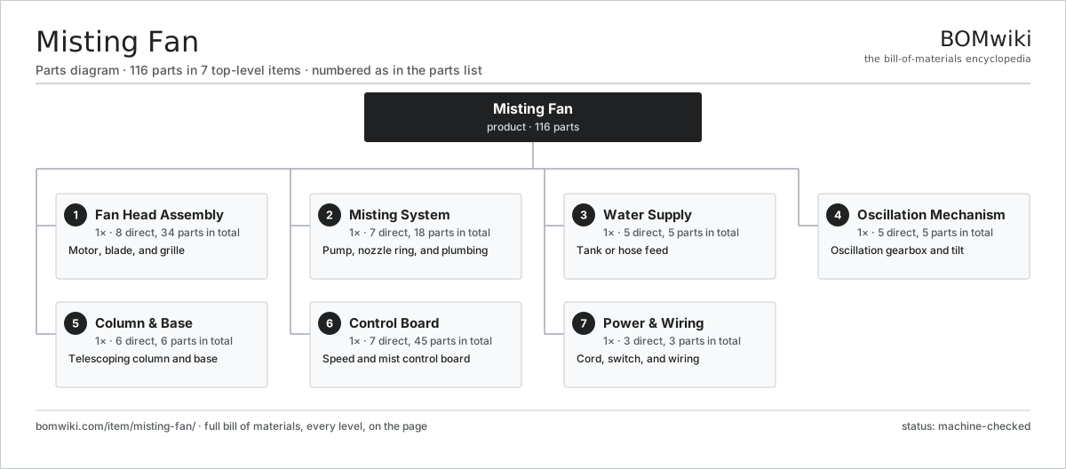
| # | Part | Qty | What it does |
|---|---|---|---|
| 1 | Fan Head Assembly 8 parts | 1× | Motor, blade, and grille |
| 2 | Misting System 7 parts | 1× | Pump, nozzle ring, and plumbing |
| 3 | Water Supply 5 parts | 1× | Tank or hose feed |
| 4 | Oscillation Mechanism 5 parts | 1× | Oscillation gearbox and tilt |
| 5 | Column & Base 6 parts | 1× | Telescoping column and base |
| 6 | Control Board 7 parts | 1× | Speed and mist control board |
| 7 | Power & Wiring 3 parts | 1× | Cord, switch, and wiring |
3D model
No 3D model yet. Have a CAD file of this? Add a 3D model. STL renders right on this page; STEP, FreeCAD, and OpenSCAD sources are welcome too (openly licensed, like all 3D models on BOMwiki).
Build & assembly graph
expand / collapse · shared sub-assemblies converge · links to related products · est. labourTap an assembly to expand/collapse · tap a part to open it · use “Open page” for any node · drag to pan, scroll to zoom.
Bill of materials for Misting Fan
7 top-level lines · 59 rows shown · 116 parts total · indented to 3 levels| # | Item / sub-assembly | Part no. | Qty/assy | Ext. qty | Parts | Type |
|---|---|---|---|---|---|---|
| 1 | Fan Head Assembly 8 parts | mf-fan-head | 1× | 1 | 34 | assembly |
| 1.1 | Fan Motor 6 parts | mf-fan-motor | 1× | 1 | 26 | assembly |
| 1.1.1 | Stator Assembly 3 parts + deeper › | stator-assembly | 1× | 1 | 3 | assembly |
| 1.1.2 | Rotor Assembly 4 parts + deeper › | rotor-assembly | 1× | 1 | 19 | assembly |
| 1.1.3 | Copper Winding | copper-winding | 1× | 1 | · | part |
| 1.1.4 | Motor Housing | motor-housing | 1× | 1 | · | part |
| 1.1.5 | Run Capacitor | mf-run-capacitor | 1× | 1 | · | part |
| 1.1.6 | Thermal Fuse | mf-thermal-fuse | 1× | 1 | · | part |
| 1.2 | Fan Blade (3-Blade) | mf-fan-blade | 1× | 1 | · | part |
| 1.3 | Front Grille | mf-front-grille | 1× | 1 | · | part |
| 1.4 | Rear Grille | mf-rear-grille | 1× | 1 | · | part |
| 1.5 | Blade Retaining Cap | mf-blade-cap | 1× | 1 | · | part |
| 1.6 | Motor Bracket | mf-motor-bracket | 1× | 1 | · | part |
| 1.7 | Ball Bearing | ball-bearing | 2× | 2 | · | part |
| 1.8 | Fastener Set | fastener-set | 1× | 1 | · | part |
| 2 | Misting System 7 parts | mf-mist-system | 1× | 1 | 18 | assembly |
| 2.1 | Misting Pump 5 parts | mf-mist-pump | 1× | 1 | 5 | assembly |
| 2.1.1 | Pump Motor | mf-pump-motor | 1× | 1 | · | part |
| 2.1.2 | Pump Diaphragm | mf-pump-diaphragm | 1× | 1 | · | part |
| 2.1.3 | Pump Check Valves | mf-pump-valves | 1× | 1 | · | part |
| 2.1.4 | Pump Head | mf-pump-head | 1× | 1 | · | part |
| 2.1.5 | O-Ring Set | oring-set | 1× | 1 | · | part |
| 2.2 | Nozzle Ring | mf-nozzle-ring | 1× | 1 | · | part |
| 2.3 | Misting Nozzle | mf-mist-nozzle | 8× | 8 | · | part |
| 2.4 | High-Pressure Supply Tube | mf-supply-tube | 1× | 1 | · | part |
| 2.5 | Inlet Filter Screen | mf-filter-screen | 1× | 1 | · | part |
| 2.6 | Pressure Relief Valve | mf-pressure-relief | 1× | 1 | · | part |
| 2.7 | O-Ring Set | oring-set | 1× | 1 | · | part |
| 3 | Water Supply 5 parts | mf-water-supply | 1× | 1 | 5 | assembly |
| 3.1 | Water Tank | mf-water-tank | 1× | 1 | · | part |
| 3.2 | Tank Cap | mf-tank-cap | 1× | 1 | · | part |
| 3.3 | Water Level Switch | mf-water-level | 1× | 1 | · | part |
| 3.4 | Hose Adapter | mf-hose-adapter | 1× | 1 | · | part |
| 3.5 | Drain Plug | mf-drain-plug | 1× | 1 | · | part |
| 4 | Oscillation Mechanism 5 parts | mf-oscillation | 1× | 1 | 5 | assembly |
| 4.1 | Oscillation Gearbox | mf-osc-gearbox | 1× | 1 | · | part |
| 4.2 | Oscillation Linkage | mf-osc-linkage | 1× | 1 | · | part |
| 4.3 | Oscillation Clutch Knob | mf-osc-clutch | 1× | 1 | · | part |
| 4.4 | Tilt Joint | mf-tilt-joint | 1× | 1 | · | part |
| 4.5 | Helical Gear Pair | gear-pair | 1× | 1 | · | part |
| 5 | Column & Base 6 parts | mf-column-base | 1× | 1 | 6 | assembly |
| 5.1 | Lower Column Tube | mf-lower-column | 1× | 1 | · | part |
| 5.2 | Upper Column Tube | mf-upper-column | 1× | 1 | · | part |
| 5.3 | Height Clamp Collar | mf-height-clamp | 1× | 1 | · | part |
| 5.4 | Weighted Base Plate | mf-base-plate | 1× | 1 | · | part |
| 5.5 | Base Cover | mf-base-cover | 1× | 1 | · | part |
| 5.6 | Fastener Set | fastener-set | 1× | 1 | · | part |
| 6 | Control Board 7 parts | mf-control | 1× | 1 | 45 | assembly |
| 6.1 | Bare PCB | pcb-bare | 1× | 1 | · | part |
| 6.2 | Microcontroller | mcu | 1× | 1 | · | part |
| 6.3 | Relay | relay | 2× | 2 | · | part |
| 6.4 | Speed Switch | mf-speed-switch | 1× | 1 | · | part |
| 6.5 | Mist Switch | mf-mist-switch | 1× | 1 | · | part |
| 6.6 | SMD Passive (R/C/L) | smd-passives | 35× | 35 | · | part |
| 6.7 | Connector | connector | 4× | 4 | · | part |
| 7 | Power & Wiring 3 parts | mf-power | 1× | 1 | 3 | assembly |
| 7.1 | Power Cord & Plug | mf-power-cord | 1× | 1 | · | part |
| 7.2 | Wire Bundle | wire-bundle | 1× | 1 | · | part |
| 7.3 | Strain Relief | mf-strain-relief | 1× | 1 | · | part |
Related products
same domain, ranked by shared parts Portable Washing Machine
167 parts · shares 13 with this page
Portable Washing Machine
167 parts · shares 13 with this page
 Top-Load Washing Machine
214 parts · shares 12 with this page
Top-Load Washing Machine
214 parts · shares 12 with this page
 Trash Compactor
85 parts · shares 11 with this page
Trash Compactor
85 parts · shares 11 with this page
 Bladeless Fan
64 parts · shares 11 with this page
Bladeless Fan
64 parts · shares 11 with this page
 Stand Fan
70 parts · shares 11 with this page
Beverage Center
133 parts · shares 12 with this page
Stand Fan
70 parts · shares 11 with this page
Beverage Center
133 parts · shares 12 with this page
Sourcing: possible vendors
Browse the supplier directory → Prices, MOQ, and lead times are algorithmic estimates, not quotes, and not claims about these companies. Company mappings are curated by keyword; est. price band $150–$3k. How estimates work| Vendor | HQ | Specialty | MOQ | Lead time |
|---|---|---|---|---|
| whirlpoolcorp.com ↗ | Benton Harbor, US | Home appliances | 1,000 units | 8–14 wks |
| bsh-group.com ↗ | Munich, DE | Appliances (Bosch, Siemens) | 1,000 units | 8–14 wks |
| electroluxgroup.com ↗ | Stockholm, SE | Home appliances | 1,000 units | 8–14 wks |
| lg.com ↗ | Seoul, KR | Appliances & electronics | 1,000 units | 8–14 wks |
|
🇨🇳Haier
haier.com ↗
|
Qingdao, CN | Home appliances | 1,000 units | 8–14 wks |
882-word article