Heat-Pump Dryer
ProductAlso known as: Heat Pump Clothes Dryer
Overview
A heat-pump clothes dryer dries laundry without venting hot, humid air outdoors. Instead of heating fresh air and throwing it away, it recirculates the same air through a sealed loop, using a refrigerant heat pump to pull moisture out of the air and reuse the heat. Because it recovers most of the heat each pass rather than dumping it, a heat-pump dryer uses roughly half the electricity of a conventional vented or condenser dryer, and because it needs no exhaust duct it can stand anywhere there is a power outlet. The trade-offs are a longer cycle, since drying air runs cooler, and a higher purchase price for the refrigerant hardware.
The structure is the Cabinet & Door, a steel Cabinet Wrapper closed by a Top Panel and Front Panel, standing on four adjustable Leveling Foot feet. Laundry goes in through the Door Assembly, a glass-fronted Door Frame with a Door Glass window, sealed against air leaks by the Door Seal. Sealing matters more here than on a vented dryer because the whole point is to keep the process air inside the loop.
Drum and tumbling
Clothes tumble in the Drum System. A galvanized steel Tumbling Drum rotates between a Front Bulkhead and Rear Bulkhead that close its ends and route air through it, riding on four Drum Support Roller rollers and sealed at each face by a Drum Felt Seal that keeps process air from escaping around the rim. Three Drum Lifter paddles inside the drum scoop the laundry up the rising side and drop it through the warm airflow, which is how the air reaches every garment instead of just the surface of a packed load.
Drive
The Drive System turns the drum and moves the air from one motor. A Drive Motor spins a poly-V Drive Belt that wraps the outside of the drum, kept taut by a spring-loaded Idler Pulley. The same motor shaft drives the Air Blower, whose Blower Wheel inside its Blower Housing pushes the recirculating air through the drum and the heat-pump coils. Tying drum and blower to one motor keeps the airflow proportional to drum rotation and saves a second motor.
The heat pump
The heart of the machine is the Heat Pump Module, a sealed refrigerant loop that works like an air conditioner turned to drying duty. The Rotary Compressor, a hermetic rotary unit, pressurizes the Refrigerant Charge (R290) R290 charge and pushes it through the loop. The hot air leaving the drum, heavy with moisture from the clothes, first passes over the cold Evaporator Coil coil. There the refrigerant absorbs heat from the air, the air cools below its dew point, and the water it carried condenses out and drips away. That same air, now cool and dry, then passes over the hot Condenser Coil coil, where the refrigerant gives its heat back, reheating the air before it returns to the drum. The Expansion Valve sets the pressure drop between the two coils that makes one cold and the other hot. Because the heat extracted at the evaporator is handed straight back at the condenser, the compressor only has to make up losses, which is the source of the efficiency. A Compressor Cooling Fan keeps the compressor itself cool and a Compressor Run Capacitor starts its motor.
Air path and lint
The recirculating air is filtered before it reaches the coils, because lint that settles on the evaporator fins would choke the heat exchange and is the leading cause of slow drying on these machines. The Air System runs the air through a coarse Lint Filter in the door opening and a Fine Lint Filter behind it, then along the Air Duct to the coils. Many machines add a Self-Clean Rinse Flap that periodically rinses the evaporator with collected condensate to wash off lint the filters miss. A Airflow Sensor watches for restriction and prompts the user to clean the filters when flow drops.
Condensate handling
The water condensed at the evaporator collects in the Condensate System. A Condensate Drip Tray under the coil catches it, and a small Condensate Pump lifts it to a removable Condensate Tank in the top of the machine that the user empties between loads. A Tank Float Switch switch stops the cycle and signals when the tank is full. For permanent installation the same pump can instead push the condensate out a Drain Hose to a standpipe, so the tank never needs emptying.
Control and use
The Control System system manages the long, low-temperature cycle. A Main Control Board with its Microcontroller runs the compressor, motor, and pump and switches the heater-free loop on and off. Drying is sensor-controlled rather than timed: Moisture Sensor Bars conductive bars in the drum read the electrical resistance across the tumbling clothes, which falls as they dry, and the control ends the cycle when the laundry reaches the chosen dryness. Two Air Temperature Sensor sensors at the loop inlet and outlet let the control protect the heat pump from overheating, and a Thermal Fuse is a last-resort cutoff. The user picks a program on the UI Board with its Program Selector Encoder dial and Capacitive Touch Key keys and reads time and status on the LCD Panel.
Variants and use
Heat-pump dryers scale from compact 7 kg units to 9 kg family machines, and the same loop appears inside heat-pump washer-dryer combinations. Some models add a small auxiliary heater to shorten the cycle at the cost of efficiency, and premium units add steam refresh, self-cleaning condensers, and connectivity. The defining hardware is constant across all of them: a tumbling drum, a single motor driving both drum and blower, a sealed refrigerant loop with an evaporator that dehumidifies and a condenser that reheats, lint filtration ahead of the coils, and a condensate path to a tank or drain.
Heat-Pump Dryer parts and their functions
8 top-level parts · 285 parts in total · full bill of materials below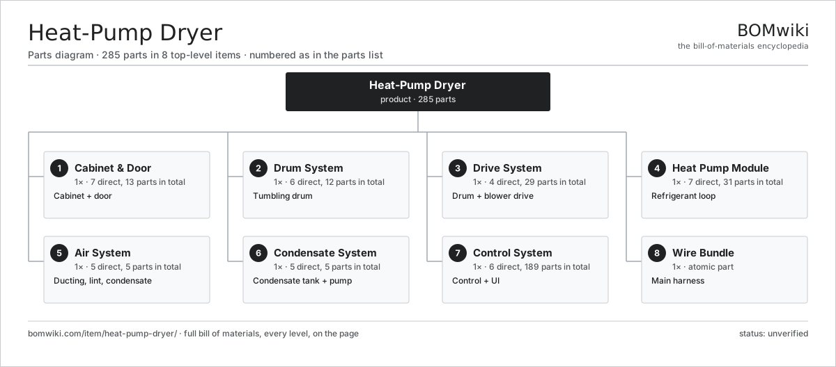
| # | Part | Qty | What it does |
|---|---|---|---|
| 1 | Cabinet & Door 7 parts | 1× | Cabinet + door |
| 2 | Drum System 6 parts | 1× | Tumbling drum |
| 3 | Drive System 4 parts | 1× | Drum + blower drive |
| 4 | Heat Pump Module 7 parts | 1× | Refrigerant loop |
| 5 | Air System 5 parts | 1× | Ducting, lint, condensate |
| 6 | Condensate System 5 parts | 1× | Condensate tank + pump |
| 7 | Control System 6 parts | 1× | Control + UI |
| 8 | Wire Bundle | 1× | Main harness |
3D model
No 3D model yet. Have a CAD file of this? Add a 3D model. STL renders right on this page; STEP, FreeCAD, and OpenSCAD sources are welcome too (openly licensed, like all 3D models on BOMwiki).
Build & assembly graph
expand / collapse · shared sub-assemblies converge · links to related products · est. labourTap an assembly to expand/collapse · tap a part to open it · use “Open page” for any node · drag to pan, scroll to zoom.
Bill of materials for Heat-Pump Dryer
8 top-level lines · 73 rows shown · 285 parts total · indented to 3 levels| # | Item / sub-assembly | Part no. | Qty/assy | Ext. qty | Parts | Type |
|---|---|---|---|---|---|---|
| 1 | Cabinet & Door 7 parts | hpd-cabinet | 1× | 1 | 13 | assembly |
| 1.1 | Cabinet Wrapper | hpd-cabinet-wrap | 1× | 1 | · | part |
| 1.2 | Top Panel | hpd-top-panel | 1× | 1 | · | part |
| 1.3 | Front Panel | hpd-front-panel | 1× | 1 | · | part |
| 1.4 | Door Assembly 4 parts | hpd-door | 1× | 1 | 4 | assembly |
| 1.4.1 | Door Frame | hpd-door-frame | 1× | 1 | · | part |
| 1.4.2 | Door Glass | hpd-door-glass | 1× | 1 | · | part |
| 1.4.3 | Door Hinge | hpd-door-hinge | 1× | 1 | · | part |
| 1.4.4 | Door Catch | hpd-door-catch | 1× | 1 | · | part |
| 1.5 | Door Seal | hpd-door-seal | 1× | 1 | · | part |
| 1.6 | Leveling Foot | hpd-leveling-foot | 4× | 4 | · | part |
| 1.7 | Fastener Set | fastener-set | 1× | 1 | · | part |
| 2 | Drum System 6 parts | hpd-drum-system | 1× | 1 | 12 | assembly |
| 2.1 | Tumbling Drum | hpd-drum | 1× | 1 | · | part |
| 2.2 | Drum Lifter | hpd-drum-lifter | 3× | 3 | · | part |
| 2.3 | Front Bulkhead | hpd-front-bulkhead | 1× | 1 | · | part |
| 2.4 | Rear Bulkhead | hpd-rear-bulkhead | 1× | 1 | · | part |
| 2.5 | Drum Felt Seal | hpd-felt-seal | 2× | 2 | · | part |
| 2.6 | Drum Support Roller | hpd-support-roller | 4× | 4 | · | part |
| 3 | Drive System 4 parts | hpd-drive-system | 1× | 1 | 29 | assembly |
| 3.1 | Drive Motor 4 parts | hpd-drive-motor | 1× | 1 | 25 | assembly |
| 3.1.1 | Stator Assembly 3 parts + deeper › | stator-assembly | 1× | 1 | 3 | assembly |
| 3.1.2 | Rotor Assembly 4 parts + deeper › | rotor-assembly | 1× | 1 | 19 | assembly |
| 3.1.3 | Motor Housing | motor-housing | 1× | 1 | · | part |
| 3.1.4 | Ball Bearing | ball-bearing | 2× | 2 | · | part |
| 3.2 | Drive Belt | drive-belt | 1× | 1 | · | part |
| 3.3 | Idler Pulley | hpd-idler-pulley | 1× | 1 | · | part |
| 3.4 | Air Blower 2 parts | hpd-blower | 1× | 1 | 2 | assembly |
| 3.4.1 | Blower Wheel | hpd-blower-wheel | 1× | 1 | · | part |
| 3.4.2 | Blower Housing | hpd-blower-housing | 1× | 1 | · | part |
| 4 | Heat Pump Module 7 parts | hpd-heat-pump | 1× | 1 | 31 | assembly |
| 4.1 | Rotary Compressor 4 parts | hpd-compressor | 1× | 1 | 25 | assembly |
| 4.1.1 | Stator Assembly 3 parts + deeper › | stator-assembly | 1× | 1 | 3 | assembly |
| 4.1.2 | Rotor Assembly 4 parts + deeper › | rotor-assembly | 1× | 1 | 19 | assembly |
| 4.1.3 | Compressor Shell | hpd-comp-shell | 1× | 1 | · | part |
| 4.1.4 | Ball Bearing | ball-bearing | 2× | 2 | · | part |
| 4.2 | Evaporator Coil | hpd-evaporator | 1× | 1 | · | part |
| 4.3 | Condenser Coil | hpd-condenser | 1× | 1 | · | part |
| 4.4 | Expansion Valve | hpd-expansion-valve | 1× | 1 | · | part |
| 4.5 | Refrigerant Charge (R290) | hpd-refrigerant | 1× | 1 | · | part |
| 4.6 | Compressor Cooling Fan | hpd-comp-fan | 1× | 1 | · | part |
| 4.7 | Compressor Run Capacitor | hpd-comp-capacitor | 1× | 1 | · | part |
| 5 | Air System 5 parts | hpd-air-system | 1× | 1 | 5 | assembly |
| 5.1 | Lint Filter | hpd-lint-filter | 1× | 1 | · | part |
| 5.2 | Fine Lint Filter | hpd-fine-lint-filter | 1× | 1 | · | part |
| 5.3 | Air Duct | hpd-air-duct | 1× | 1 | · | part |
| 5.4 | Self-Clean Rinse Flap | hpd-self-clean-flap | 1× | 1 | · | part |
| 5.5 | Airflow Sensor | hpd-airflow-sensor | 1× | 1 | · | part |
| 6 | Condensate System 5 parts | hpd-water-system | 1× | 1 | 5 | assembly |
| 6.1 | Condensate Drip Tray | hpd-drip-tray | 1× | 1 | · | part |
| 6.2 | Condensate Pump | hpd-condensate-pump | 1× | 1 | · | part |
| 6.3 | Condensate Tank | hpd-condensate-tank | 1× | 1 | · | part |
| 6.4 | Tank Float Switch | hpd-tank-float | 1× | 1 | · | part |
| 6.5 | Drain Hose | hpd-drain-hose | 1× | 1 | · | part |
| 7 | Control System 6 parts | hpd-control | 1× | 1 | 189 | assembly |
| 7.1 | Main Control Board 6 parts | hpd-main-board | 1× | 1 | 150 | assembly |
| 7.1.1 | Bare PCB | pcb-bare | 1× | 1 | · | part |
| 7.1.2 | Microcontroller | mcu | 1× | 1 | · | part |
| 7.1.3 | Relay | relay | 5× | 5 | · | part |
| 7.1.4 | Triac | triac | 1× | 1 | · | part |
| 7.1.5 | Connector | connector | 12× | 12 | · | part |
| 7.1.6 | SMD Passive (R/C/L) | smd-passives | 130× | 130 | · | part |
| 7.2 | UI Board 5 parts | hpd-ui-board | 1× | 1 | 34 | assembly |
| 7.2.1 | Bare PCB | pcb-bare | 1× | 1 | · | part |
| 7.2.2 | Microcontroller | mcu | 1× | 1 | · | part |
| 7.2.3 | Program Selector Encoder | hpd-rotary-encoder | 1× | 1 | · | part |
| 7.2.4 | Capacitive Touch Key | hpd-touch-key | 6× | 6 | · | part |
| 7.2.5 | SMD Passive (R/C/L) | smd-passives | 25× | 25 | · | part |
| 7.3 | LCD Panel | lcd-panel | 1× | 1 | · | part |
| 7.4 | Moisture Sensor Bars | hpd-moisture-sensor | 1× | 1 | · | part |
| 7.5 | Air Temperature Sensor | hpd-temp-sensor | 2× | 2 | · | part |
| 7.6 | Thermal Fuse | thermal-fuse | 1× | 1 | · | part |
| 8 | Wire Bundle | wire-bundle | 1× | 1 | · | part |
Related products
same domain, ranked by shared parts Front-Load Washing Machine
370 parts · shares 14 with this page
Front-Load Washing Machine
370 parts · shares 14 with this page
 Top-Load Washing Machine
214 parts · shares 13 with this page
Top-Load Washing Machine
214 parts · shares 13 with this page
 Washing Machine
185 parts · shares 13 with this page
Washing Machine
185 parts · shares 13 with this page
 Dishwasher
146 parts · shares 12 with this page
Dishwasher
146 parts · shares 12 with this page
 Refrigerator
95 parts · shares 12 with this page
Refrigerator
95 parts · shares 12 with this page
 Clothes Dryer
240 parts · shares 13 with this page
Clothes Dryer
240 parts · shares 13 with this page
Sourcing: possible vendors
Browse the supplier directory → Prices, MOQ, and lead times are algorithmic estimates, not quotes, and not claims about these companies. Company mappings are curated by keyword; est. price band $150–$3k. How estimates work| Vendor | HQ | Specialty | MOQ | Lead time |
|---|---|---|---|---|
| whirlpoolcorp.com ↗ | Benton Harbor, US | Home appliances | 1,000 units | 8–14 wks |
| bsh-group.com ↗ | Munich, DE | Appliances (Bosch, Siemens) | 1,000 units | 8–14 wks |
| electroluxgroup.com ↗ | Stockholm, SE | Home appliances | 1,000 units | 8–14 wks |
| lg.com ↗ | Seoul, KR | Appliances & electronics | 1,000 units | 8–14 wks |
|
🇨🇳Haier
haier.com ↗
|
Qingdao, CN | Home appliances | 1,000 units | 8–14 wks |
1,010-word article