Electric Hole Punch
ProductOverview
An electric hole punch is a heavy-duty desktop machine used in busy office environments to automatically perforate stacks of paper with precision spacing, preparing documents for binding into binders or folders. Unlike manual punch tools that require user strength and produce fatigue, the electric punch uses a motor-driven cam mechanism to deliver consistent, powerful strikes, handling up to 20–30 sheets in a single stroke.
The machine consists of a motor that drives a cam shaft, a punch head assembly carrying two or three hardened-steel dies, a paper guide fence for alignment, and a foot pedal or button control activating each punch stroke. Dies sharpen easily and last decades. A removable chip tray collects waste without stopping production, and safety interlocks prevent operation if protective guards are open.
How it works
Pressing the Foot Pedal sends a signal to the Electromagnetic Clutch, which engages the running Electric Motor to the Cam Shaft. The rotating cam lobe pushes the Cam Follower Arm downward, descending the Punch Head Assembly. The hardened Punch Die teeth punch through the paper stack onto the hardened Punch Baseplate backing, creating clean, aligned holes. The Die Return Spring returns the punch die to rest position when the cam lobe releases the follower.
Paper is positioned using the Guide & Fence: the Front Edge Guide stops the leading edge at a fixed distance, and the Side Guide Rail rails guide the paper's side edge, ensuring correct hole spacing and alignment across batches. The Alignment Ruler provides a visual reference for hole position setup.
Waste paper chads fall through the Waste Chute into the removable Chip Bucket, which can be emptied without disassembling the machine. The Protective Guard encloses the punch area for safety, and the Guard Safety Interlock on the guard prevents operation if it is opened, protecting the operator's hands from the descending Punch Head Assembly.
The Circuit Breaker protects the Electric Motor from overload if the punch dies jam or the stack exceeds rated capacity. The Welded Chassis provides stable support, and Vibration Isolator isolators dampen vibration during the punch stroke, reducing desk rattle and protecting surfaces.
Electric Hole Punch parts and their functions
8 top-level parts · 43 parts in total · full bill of materials below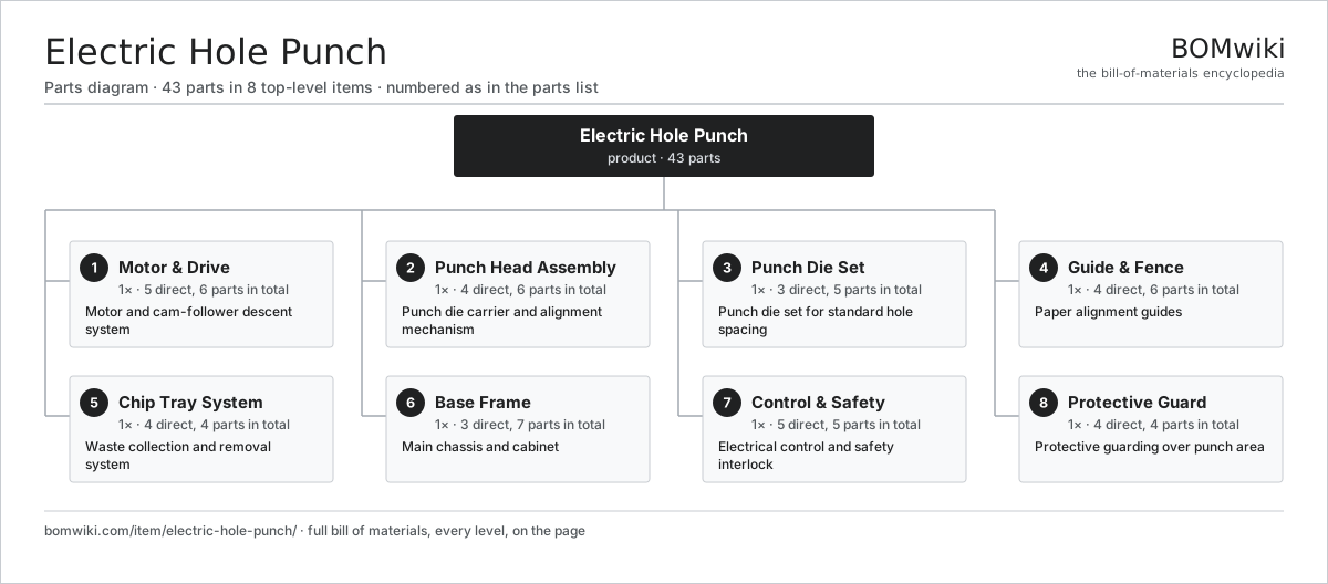
| # | Part | Qty | What it does |
|---|---|---|---|
| 1 | Motor & Drive 5 parts | 1× | Motor and cam-follower descent system |
| 2 | Punch Head Assembly 4 parts | 1× | Punch die carrier and alignment mechanism |
| 3 | Punch Die Set 3 parts | 1× | Punch die set for standard hole spacing |
| 4 | Guide & Fence 4 parts | 1× | Paper alignment guides |
| 5 | Chip Tray System 4 parts | 1× | Waste collection and removal system |
| 6 | Base Frame 3 parts | 1× | Main chassis and cabinet |
| 7 | Control & Safety 5 parts | 1× | Electrical control and safety interlock |
| 8 | Protective Guard 4 parts | 1× | Protective guarding over punch area |
3D model
No 3D model yet. Have a CAD file of this? Add a 3D model. STL renders right on this page; STEP, FreeCAD, and OpenSCAD sources are welcome too (openly licensed, like all 3D models on BOMwiki).
Build & assembly graph
expand / collapse · shared sub-assemblies converge · links to related products · est. labourTap an assembly to expand/collapse · tap a part to open it · use “Open page” for any node · drag to pan, scroll to zoom.
Bill of materials for Electric Hole Punch
8 top-level lines · 40 rows shown · 43 parts total · indented to 3 levels| # | Item / sub-assembly | Part no. | Qty/assy | Ext. qty | Parts | Type |
|---|---|---|---|---|---|---|
| 1 | Motor & Drive 5 parts | electric-hole-punch-motor-drive | 1× | 1 | 6 | assembly |
| 1.1 | Electric Motor | electric-hole-punch-motor | 1× | 1 | · | part |
| 1.2 | Electromagnetic Clutch | electric-hole-punch-clutch | 1× | 1 | · | part |
| 1.3 | Cam Shaft | electric-hole-punch-cam-shaft | 1× | 1 | · | part |
| 1.4 | Cam Follower Arm | electric-hole-punch-follower-arm | 1× | 1 | · | part |
| 1.5 | Fastener Set | fastener-set | 2× | 2 | · | part |
| 2 | Punch Head Assembly 4 parts | electric-hole-punch-punch-head | 1× | 1 | 6 | assembly |
| 2.1 | Die Holder Block | electric-hole-punch-die-holder | 1× | 1 | · | part |
| 2.2 | Punch Baseplate | electric-hole-punch-punch-plate | 1× | 1 | · | part |
| 2.3 | Ball Bearing | ball-bearing | 2× | 2 | · | part |
| 2.4 | Fastener Set | fastener-set | 2× | 2 | · | part |
| 3 | Punch Die Set 3 parts | electric-hole-punch-dies | 1× | 1 | 5 | assembly |
| 3.1 | Punch Die | electric-hole-punch-die-unit | 2× | 2 | · | part |
| 3.2 | Die Return Spring | electric-hole-punch-die-spring | 2× | 2 | · | part |
| 3.3 | Fastener Set | fastener-set | 1× | 1 | · | part |
| 4 | Guide & Fence 4 parts | electric-hole-punch-guide-fence | 1× | 1 | 6 | assembly |
| 4.1 | Front Edge Guide | electric-hole-punch-front-guide | 1× | 1 | · | part |
| 4.2 | Side Guide Rail | electric-hole-punch-side-fence | 2× | 2 | · | part |
| 4.3 | Alignment Ruler | electric-hole-punch-ruler-strip | 1× | 1 | · | part |
| 4.4 | Fastener Set | fastener-set | 2× | 2 | · | part |
| 5 | Chip Tray System 4 parts | electric-hole-punch-chip-tray | 1× | 1 | 4 | assembly |
| 5.1 | Chip Bucket | electric-hole-punch-tray-bucket | 1× | 1 | · | part |
| 5.2 | Waste Chute | electric-hole-punch-chute | 1× | 1 | · | part |
| 5.3 | Tray Hinge | electric-hole-punch-tray-hinge | 1× | 1 | · | part |
| 5.4 | Fastener Set | fastener-set | 1× | 1 | · | part |
| 6 | Base Frame 3 parts | electric-hole-punch-base-frame | 1× | 1 | 7 | assembly |
| 6.1 | Welded Chassis | electric-hole-punch-welded-base | 1× | 1 | · | part |
| 6.2 | Vibration Isolator | electric-hole-punch-foot-pad | 4× | 4 | · | part |
| 6.3 | Fastener Set | fastener-set | 2× | 2 | · | part |
| 7 | Control & Safety 5 parts | electric-hole-punch-control-switch | 1× | 1 | 5 | assembly |
| 7.1 | Foot Pedal | electric-hole-punch-foot-pedal | 1× | 1 | · | part |
| 7.2 | Circuit Breaker | electric-hole-punch-circuit-breaker | 1× | 1 | · | part |
| 7.3 | Guard Safety Interlock | electric-hole-punch-safety-switch | 1× | 1 | · | part |
| 7.4 | Relay | relay | 1× | 1 | · | part |
| 7.5 | Fastener Set | fastener-set | 1× | 1 | · | part |
| 8 | Protective Guard 4 parts | electric-hole-punch-guard | 1× | 1 | 4 | assembly |
| 8.1 | Guard Panel | electric-hole-punch-guard-panel | 1× | 1 | · | part |
| 8.2 | Guard Frame | electric-hole-punch-guard-frame | 1× | 1 | · | part |
| 8.3 | Guard Hinge | electric-hole-punch-hinge-assembly | 1× | 1 | · | part |
| 8.4 | Fastener Set | fastener-set | 1× | 1 | · | part |
Something wrong in this list? Report a problem with this BOM.
Related products
same domain, ranked by shared parts Cash Deposit Machine
64 parts · shares 1 with this page
 Cash Register
165 parts · shares 1 with this page
 Checkout Lane Conveyor
63 parts · shares 1 with this page
Coin Counting Kiosk
63 parts · shares 1 with this page
 Coin Wrapping Machine
70 parts · shares 1 with this page
Sourcing: possible vendors
Browse the supplier directory → Prices, MOQ, and lead times are algorithmic estimates, not quotes, and not claims about these companies. Company mappings are curated by keyword; est. price band $50–$15k. How estimates work| Vendor | HQ | Specialty | MOQ | Lead time |
|---|---|---|---|---|
|
🇯🇵Canon
canon.com ↗
|
Tokyo, JP | Imaging & optics | 500 units | 8–12 wks |
|
🇯🇵Ricoh
ricoh.com ↗
|
Tokyo, JP | Office imaging | 500 units | 8–12 wks |
|
🇺🇸Xerox
xerox.com ↗
|
Norwalk, US | Printers & copiers | 500 units | 8–12 wks |
|
🇯🇵Epson
epson.com ↗
|
Suwa, JP | Printers & projectors | 500 units | 8–12 wks |
|
🇯🇵Brother
brother.com ↗
|
Nagoya, JP | Printers & sewing | 500 units | 8–12 wks |
410-word article