Money Counting Machine
ProductOverview
A money-counting machine tallies a stack of banknotes quickly and accurately, and on better models also checks each note for authenticity and reads its denomination. Notes are fed from a hopper, separated one at a time, flung past a bank of sensors, and stacked in an output pocket while a counter ticks up. By replacing hand counting it removes both the labour and the miscounts of cash handling in banks, retail, and casinos.
The machine is a compact desktop unit with an angled input on top and a catch pocket on the front. The Housing holds the body, hopper, and stacker shells. The Feed System separates and launches notes, the Note Transport guides them through the sensor zone, and the Detection Array block carries the counterfeit and counting sensors. Counted notes land via the Stacker, with results shown on the operator Operator Display and a Customer Display facing the payer, all fed by the Power Supply.
How it works
A stack is dropped into the hopper and the Feed System roller, working against a friction pad, peels off the bottom note and accelerates it into the path. The Note Transport rollers carry it at constant speed through the Detection Array zone in a few milliseconds.
There, a contact image sensor reads each note's pattern while ultraviolet, magnetic, and infrared sensors check the security features: UV-fluorescent fibres, magnetic ink, and IR-transparent zones that genuine notes carry and most fakes lack. The Main Control Board compares these signals against stored templates to verify the note, identify its denomination, and increment the count. A double-note or chained-note error halts the run. Verified notes are thrown by the Stacker wheel into the front pocket in a neat fan. The running total and any suspect-note flag appear on the Operator Display, while the Customer Display shows the customer the same figure.
Money Counting Machine parts and their functions
10 top-level parts · 102 parts in total · full bill of materials below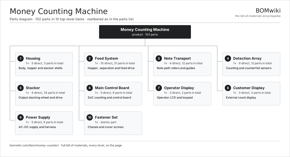
| # | Part | Qty | What it does |
|---|---|---|---|
| 1 | Housing 3 parts | 1× | Body, hopper and stacker shells |
| 2 | Feed System 10 parts | 1× | Hopper, separation and feed drive |
| 3 | Note Transport 4 parts | 1× | Note path rollers and guides |
| 4 | Detection Array 9 parts | 1× | Counting and counterfeit sensors |
| 5 | Stacker 4 parts | 1× | Output stacking wheel and drive |
| 6 | Main Control Board 5 parts | 1× | SoC counting and control board |
| 7 | Operator Display 2 parts | 1× | Operator LCD and keypad |
| 8 | Customer Display 3 parts | 1× | External count display |
| 9 | Power Supply 5 parts | 1× | AC-DC supply and harness |
| 10 | Fastener Set | 1× | Chassis and cover screws |
3D model
No 3D model yet. Have a CAD file of this? Add a 3D model. STL renders right on this page; STEP, FreeCAD, and OpenSCAD sources are welcome too (openly licensed, like all 3D models on BOMwiki).
Build & assembly graph
expand / collapse · shared sub-assemblies converge · links to related products · est. labourTap an assembly to expand/collapse · tap a part to open it · use “Open page” for any node · drag to pan, scroll to zoom.
Bill of materials for Money Counting Machine
10 top-level lines · 69 rows shown · 102 parts total · indented to 3 levels| # | Item / sub-assembly | Part no. | Qty/assy | Ext. qty | Parts | Type |
|---|---|---|---|---|---|---|
| 1 | Housing 3 parts | money-counter-housing | 1× | 1 | 3 | assembly |
| 1.1 | Body Shell | money-counter-body-shell | 1× | 1 | · | part |
| 1.2 | Input Hopper | money-counter-hopper | 1× | 1 | · | part |
| 1.3 | Stacker Pocket | money-counter-stacker-pocket | 1× | 1 | · | part |
| 2 | Feed System 10 parts | money-counter-feed-system | 1× | 1 | 31 | assembly |
| 2.1 | Hopper Feed Guide | money-counter-hopper-guide | 1× | 1 | · | part |
| 2.2 | Adjustable Feed Guide | money-counter-adjustable-guide | 1× | 1 | · | part |
| 2.3 | Feed Roller | money-counter-feed-roller | 1× | 1 | · | part |
| 2.4 | Friction Separation Roller | money-counter-friction-roller | 1× | 1 | · | part |
| 2.5 | Stator Assembly 3 parts | stator-assembly | 1× | 1 | 3 | assembly |
| 2.5.1 | Stator Core (laminations) | stator-core | 1× | 1 | · | part |
| 2.5.2 | Copper Winding | copper-winding | 1× | 1 | · | part |
| 2.5.3 | Slot Insulation | stator-insulation | 1× | 1 | · | part |
| 2.6 | Rotor Assembly 4 parts | rotor-assembly | 1× | 1 | 19 | assembly |
| 2.6.1 | Rotor Shaft | rotor-shaft | 1× | 1 | · | part |
| 2.6.2 | Rotor Core | rotor-core | 1× | 1 | · | part |
| 2.6.3 | Neodymium Magnet | neodymium-magnet | 16× | 16 | · | part |
| 2.6.4 | Ball Bearing | ball-bearing | 1× | 1 | · | part |
| 2.7 | Motor Housing | motor-housing | 1× | 1 | · | part |
| 2.8 | Drive Belt | drive-belt | 1× | 1 | · | part |
| 2.9 | Helical Gear Pair | gear-pair | 1× | 1 | · | part |
| 2.10 | Ball Bearing | ball-bearing | 2× | 2 | · | part |
| 3 | Note Transport 4 parts | money-counter-transport | 1× | 1 | 12 | assembly |
| 3.1 | Transport Roller | money-counter-transport-roller | 4× | 4 | · | part |
| 3.2 | Drive Belt | drive-belt | 2× | 2 | · | part |
| 3.3 | Path Guide Plate | money-counter-path-guide | 2× | 2 | · | part |
| 3.4 | Ball Bearing | ball-bearing | 4× | 4 | · | part |
| 4 | Detection Array 9 parts | money-counter-detection | 1× | 1 | 12 | assembly |
| 4.1 | Counting Sensor (IR/Optical) | money-counter-count-sensor | 2× | 2 | · | part |
| 4.2 | Speed Encoder | money-counter-speed-encoder | 1× | 1 | · | part |
| 4.3 | UV LED | money-counter-uv-led | 2× | 2 | · | part |
| 4.4 | UV Fluorescence Sensor | money-counter-uv-sensor | 1× | 1 | · | part |
| 4.5 | Magnetic (MG) Head | money-counter-mg-head | 1× | 1 | · | part |
| 4.6 | CMOS Image Sensor | image-sensor | 1× | 1 | · | part |
| 4.7 | Dimension Sensor | money-counter-dimension-sensor | 2× | 2 | · | part |
| 4.8 | Bare PCB | pcb-bare | 1× | 1 | · | part |
| 4.9 | SMD Passive (R/C/L) | smd-passives | 1× | 1 | · | part |
| 5 | Stacker 4 parts | money-counter-stacker | 1× | 1 | 24 | assembly |
| 5.1 | Stacker Wheel | money-counter-stacker-wheel | 1× | 1 | · | part |
| 5.2 | Stator Assembly 3 parts | stator-assembly | 1× | 1 | 3 | assembly |
| 5.2.1 | Stator Core (laminations) | stator-core | 1× | 1 | · | part |
| 5.2.2 | Copper Winding | copper-winding | 1× | 1 | · | part |
| 5.2.3 | Slot Insulation | stator-insulation | 1× | 1 | · | part |
| 5.3 | Rotor Assembly 4 parts | rotor-assembly | 1× | 1 | 19 | assembly |
| 5.3.1 | Rotor Shaft | rotor-shaft | 1× | 1 | · | part |
| 5.3.2 | Rotor Core | rotor-core | 1× | 1 | · | part |
| 5.3.3 | Neodymium Magnet | neodymium-magnet | 16× | 16 | · | part |
| 5.3.4 | Ball Bearing | ball-bearing | 1× | 1 | · | part |
| 5.4 | Ball Bearing | ball-bearing | 1× | 1 | · | part |
| 6 | Main Control Board 5 parts | money-counter-main-board | 1× | 1 | 8 | assembly |
| 6.1 | Bare PCB | pcb-bare | 1× | 1 | · | part |
| 6.2 | Compute SoC Module | soc-module | 1× | 1 | · | part |
| 6.3 | Microcontroller | mcu | 1× | 1 | · | part |
| 6.4 | SMD Passive (R/C/L) | smd-passives | 1× | 1 | · | part |
| 6.5 | Connector | connector | 4× | 4 | · | part |
| 7 | Operator Display 2 parts | money-counter-display | 1× | 1 | 2 | assembly |
| 7.1 | LCD Panel | lcd-panel | 1× | 1 | · | part |
| 7.2 | Keypad | money-counter-keypad | 1× | 1 | · | part |
| 8 | Customer Display 3 parts | money-counter-customer-display | 1× | 1 | 3 | assembly |
| 8.1 | LCD Panel | lcd-panel | 1× | 1 | · | part |
| 8.2 | Wire Bundle | wire-bundle | 1× | 1 | · | part |
| 8.3 | Connector | connector | 1× | 1 | · | part |
| 9 | Power Supply 5 parts | money-counter-power-supply | 1× | 1 | 6 | assembly |
| 9.1 | Bare PCB | pcb-bare | 1× | 1 | · | part |
| 9.2 | SMD Passive (R/C/L) | smd-passives | 1× | 1 | · | part |
| 9.3 | Power Cord | money-counter-power-cord | 1× | 1 | · | part |
| 9.4 | Wire Bundle | wire-bundle | 1× | 1 | · | part |
| 9.5 | Connector | connector | 2× | 2 | · | part |
| 10 | Fastener Set | fastener-set | 1× | 1 | · | part |
Something wrong in this list? Report a problem with this BOM.
Related products
same domain, ranked by shared parts Photocopier (MFP)
210 parts · shares 15 with this page
 Key Cutting Machine
63 parts · shares 11 with this page
 Franking Machine
441 parts · shares 15 with this page
 Document Scanner
79 parts · shares 14 with this page
 Cash Register
165 parts · shares 14 with this page
Sourcing: possible vendors
Browse the supplier directory → Prices, MOQ, and lead times are algorithmic estimates, not quotes, and not claims about these companies. Company mappings are curated by keyword; est. price band $50–$15k. How estimates work| Vendor | HQ | Specialty | MOQ | Lead time |
|---|---|---|---|---|
|
🇯🇵Canon
canon.com ↗
|
Tokyo, JP | Imaging & optics | 500 units | 8–12 wks |
|
🇯🇵Ricoh
ricoh.com ↗
|
Tokyo, JP | Office imaging | 500 units | 8–12 wks |
|
🇺🇸Xerox
xerox.com ↗
|
Norwalk, US | Printers & copiers | 500 units | 8–12 wks |
|
🇯🇵Epson
epson.com ↗
|
Suwa, JP | Printers & projectors | 500 units | 8–12 wks |
|
🇯🇵Brother
brother.com ↗
|
Nagoya, JP | Printers & sewing | 500 units | 8–12 wks |
337-word article