Pouch Laminator
ProductOverview
A pouch laminator seals a document between two sheets of plastic film to protect it and give it a rigid, wipe-clean finish. The document is placed inside a folded pouch coated on the inside with heat-activated adhesive; the machine pulls the pouch between heated rollers that melt the adhesive and press the layers permanently together. The result is a sealed, water-resistant card or sheet. A four-roller arrangement spreads the heat and pressure over a longer contact zone, which reduces wrinkling and trapped bubbles compared with two-roller machines.
The machine is a low, slot-fronted box. The Housing & Shell is the outer shell and inner sheet-metal frame holding everything in alignment. The two Heated Roller Assembly units carry the silicone rollers and their internal heaters. The Roller Drive train turns the rollers in unison, fed by the Feed Tray & Guide and caught by the Exit Tray. The Control Board regulates temperature and speed, and the Power Input brings in mains power.
How it works
At power-up the Control Board energises the cartridge heaters inside the Heated Roller Assembly rollers and waits for a thermistor to report that the silicone surfaces have reached the set temperature, signalling ready. A pouch holding the document is pushed sealed-edge-first into the Feed Tray & Guide so the rollers grip it squarely.
The Roller Drive motor and gears rotate the rollers, drawing the pouch through the nip. The first roller pair applies heat, melting the adhesive layer; the second pair applies cooling pressure that bonds the film and squeezes out air, leaving a flat, bubble-free seal. The laminated sheet emerges onto the Exit Tray, still warm, and flattens as it cools. A cold mode keeps the heaters off for pressure-sensitive pouches, and a jam-release lever lifts the roller pressure so a mis-fed pouch can be reversed out without damaging the rollers.
Pouch Laminator parts and their functions
8 top-level parts · 57 parts in total · full bill of materials below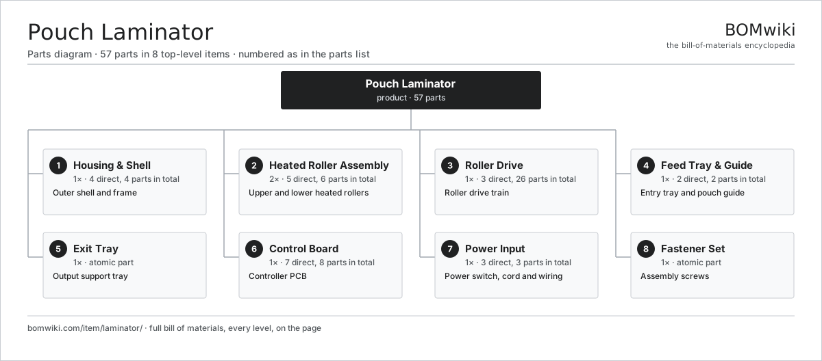
| # | Part | Qty | What it does |
|---|---|---|---|
| 1 | Housing & Shell 4 parts | 1× | Outer shell and frame |
| 2 | Heated Roller Assembly 5 parts | 2× | Upper and lower heated rollers |
| 3 | Roller Drive 3 parts | 1× | Roller drive train |
| 4 | Feed Tray & Guide 2 parts | 1× | Entry tray and pouch guide |
| 5 | Exit Tray | 1× | Output support tray |
| 6 | Control Board 7 parts | 1× | Controller PCB |
| 7 | Power Input 3 parts | 1× | Power switch, cord and wiring |
| 8 | Fastener Set | 1× | Assembly screws |
3D model
No 3D model yet. Have a CAD file of this? Add a 3D model. STL renders right on this page; STEP, FreeCAD, and OpenSCAD sources are welcome too (openly licensed, like all 3D models on BOMwiki).
Build & assembly graph
expand / collapse · shared sub-assemblies converge · links to related products · est. labourTap an assembly to expand/collapse · tap a part to open it · use “Open page” for any node · drag to pan, scroll to zoom.
Bill of materials for Pouch Laminator
8 top-level lines · 35 rows shown · 57 parts total · indented to 3 levels| # | Item / sub-assembly | Part no. | Qty/assy | Ext. qty | Parts | Type |
|---|---|---|---|---|---|---|
| 1 | Housing & Shell 4 parts | laminator-housing | 1× | 1 | 4 | assembly |
| 1.1 | Upper Shell | laminator-upper-shell | 1× | 1 | · | part |
| 1.2 | Lower Shell | laminator-lower-shell | 1× | 1 | · | part |
| 1.3 | Inner Chassis | laminator-inner-chassis | 1× | 1 | · | part |
| 1.4 | Fastener Set | fastener-set | 1× | 1 | · | part |
| 2 | Heated Roller Assembly 5 parts | laminator-heated-roller-assy | 2× | 2 | 6 | assembly |
| 2.1 | Silicone Roller | laminator-silicone-roller | 1× | 2 | · | part |
| 2.2 | Heating Element | heating-element | 1× | 2 | · | part |
| 2.3 | Thermal Fuse | thermal-fuse | 1× | 2 | · | part |
| 2.4 | Thermistor | laminator-thermistor | 1× | 2 | · | part |
| 2.5 | Ball Bearing | ball-bearing | 2× | 4 | · | part |
| 3 | Roller Drive 3 parts | laminator-drive | 1× | 1 | 26 | assembly |
| 3.1 | Drive Motor 3 parts | laminator-drive-motor | 1× | 1 | 23 | assembly |
| 3.1.1 | Stator Assembly 3 parts + deeper › | stator-assembly | 1× | 1 | 3 | assembly |
| 3.1.2 | Rotor Assembly 4 parts + deeper › | rotor-assembly | 1× | 1 | 19 | assembly |
| 3.1.3 | Motor Housing | motor-housing | 1× | 1 | · | part |
| 3.2 | Helical Gear Pair | gear-pair | 1× | 1 | · | part |
| 3.3 | Roller Drive Gear | laminator-roller-gear | 2× | 2 | · | part |
| 4 | Feed Tray & Guide 2 parts | laminator-feed-tray | 1× | 1 | 2 | assembly |
| 4.1 | Tray Plate | laminator-tray-plate | 1× | 1 | · | part |
| 4.2 | Pouch Guide | laminator-pouch-guide | 1× | 1 | · | part |
| 5 | Exit Tray | laminator-exit-tray | 1× | 1 | · | part |
| 6 | Control Board 7 parts | laminator-control-board | 1× | 1 | 8 | assembly |
| 6.1 | Bare PCB | pcb-bare | 1× | 1 | · | part |
| 6.2 | Microcontroller | mcu | 1× | 1 | · | part |
| 6.3 | Ready LED | laminator-ready-led | 1× | 1 | · | part |
| 6.4 | Hot/Cold Switch | laminator-mode-switch | 1× | 1 | · | part |
| 6.5 | Reverse Button | laminator-reverse-button | 1× | 1 | · | part |
| 6.6 | Jam-Release Lever | laminator-jam-lever | 1× | 1 | · | part |
| 6.7 | Connector | connector | 2× | 2 | · | part |
| 7 | Power Input 3 parts | laminator-power-input | 1× | 1 | 3 | assembly |
| 7.1 | Power Switch | laminator-power-switch | 1× | 1 | · | part |
| 7.2 | Power Cord | laminator-power-cord | 1× | 1 | · | part |
| 7.3 | Wire Bundle | wire-bundle | 1× | 1 | · | part |
| 8 | Fastener Set | fastener-set | 1× | 1 | · | part |
Something wrong in this list? Report a problem with this BOM.
Related products
same domain, ranked by shared parts Photocopier (MFP)
210 parts · shares 13 with this page
 Key Cutting Machine
63 parts · shares 11 with this page
 Cash Register
165 parts · shares 12 with this page
 Folding & Inserting Machine
151 parts · shares 12 with this page
 Handheld Label Maker
54 parts · shares 12 with this page
 ID Card Printer
71 parts · shares 12 with this page
Sourcing: possible vendors
Browse the supplier directory → Prices, MOQ, and lead times are algorithmic estimates, not quotes, and not claims about these companies. Company mappings are curated by keyword; est. price band $50–$15k. How estimates work| Vendor | HQ | Specialty | MOQ | Lead time |
|---|---|---|---|---|
|
🇯🇵Canon
canon.com ↗
|
Tokyo, JP | Imaging & optics | 500 units | 8–12 wks |
|
🇯🇵Ricoh
ricoh.com ↗
|
Tokyo, JP | Office imaging | 500 units | 8–12 wks |
|
🇺🇸Xerox
xerox.com ↗
|
Norwalk, US | Printers & copiers | 500 units | 8–12 wks |
|
🇯🇵Epson
epson.com ↗
|
Suwa, JP | Printers & projectors | 500 units | 8–12 wks |
|
🇯🇵Brother
brother.com ↗
|
Nagoya, JP | Printers & sewing | 500 units | 8–12 wks |
325-word article