Robotic Case Erector
ProductOverview
A robotic case erector turns flat corrugated blanks into open, bottom-sealed boxes ready for a packing line to fill. It sits at the head of a packaging line, ahead of the case packer, and its output rate sets the pace for everything downstream. The robotic version replaces the fixed cam-driven erector with a compact Pick Robot, which trades a little peak speed for a much wider range of case sizes and faster changeover. That flexibility suits lines that run several pack formats, where a fixed erector would need a tooling change for each one.
How it works
Flat blanks are loaded into the Blank Magazine, an inclined hopper that holds a few hundred and feeds them forward on a belt against spring Retaining Fingers fingers that let one peel off at a time. The Pick Robot, a four-axis arm with a vacuum Pick Tool, grips the face of the front blank and pulls it from the magazine. As it lifts, a Swivel Joint in the tool breaks the blank square, opening the folded tube into a box cross-section in the same motion. Doing the pick and the opening together is what keeps the cycle short.
The arm presents the opened blank to the Forming Mandrel, a box-shaped tool the case is pushed onto so its walls set square. Squaring Guide rails hold the shape while the bottom flaps are dealt with. The Bottom Flap Folder then closes the four bottom flaps in the correct order: the two short minor flaps fold in first, then the two long major flaps fold over them, the standard sequence that gives the bottom its strength. Each fold is a cam-timed plate driven by a pneumatic actuator.
Sealing the bottom
With the flaps held closed, the Bottom Sealing Head seals the bottom. A roll of pressure-sensitive tape pays off the Tape Cartridge under brake tension, an applicator roller presses a leading strip onto the case, and as the case moves through, the tape lays across the flap seam. A Cut-off Blade blade severs the tape at the trailing edge and a sprung Wipe-Down Arm presses it flat so it bonds. The erected, sealed case is pushed onto the Case Discharge belt and runs upright to the packer. Tape sealing is the most common method; hot-melt glue is the alternative on lines that want a tamper-evident or higher-strength bottom.
Materials and construction
The pick arm links are light cast aluminium because the duty is fast and the payload is only a corrugated blank, so the arm is sized for acceleration rather than load. The forming mandrel and squaring guides are hard-anodised aluminium that slides against corrugated without abrading it, and the fold plates are faced steel. The tape head rollers are rubber-covered for grip on the tape adhesive. The whole cell sits on a welded steel Main Weldment so the magazine, mandrel, and tape head hold a common datum, which is what lets the bottom seam land consistently across the flap joint. Guarding is interlocked sheet metal; opening the Access Gate drops the safety circuit.
Control and changeover
The Control Cabinet cabinet holds a robot motion controller for the pick arm, a cell Cell PLC sequencing the magazine, mandrel, folders, and tape head, the servo drives, and the operator Operator HMI. Case size is stored as a recipe: changing to a new box is a recipe selection plus a quick adjustment of the squaring guides and tape position, typically under five minutes, against the longer mechanical changeover a fixed erector needs. The pick arm's taught path adapts to the blank dimensions automatically, so a wide size range runs on one machine.
Variants and use
The main variants are by seal method and by speed. Tape-seal erectors like this one are the common choice; hot-melt versions add a glue applicator in place of the tape head and suit cases that must be tamper-evident or stacked heavy. Higher-rate lines use a continuous-motion cam erector instead of a robot when the format range is narrow and peak speed matters more than flexibility. In service the magazine is topped up with blanks, the tape rolls are changed when low, and maintenance focuses on the vacuum cups, the tape head rollers, and the cut-off blade, all wear items. Because the bottom seal is what holds a filled case together, the wipe-down and tape tension are the settings most worth checking, since a poorly wiped seam is the usual cause of a case failing under load downstream.
Robotic Case Erector parts and their functions
8 top-level parts · 799 parts in total · full bill of materials below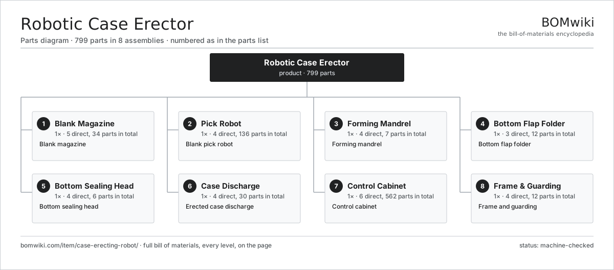
| # | Part | Qty | What it does |
|---|---|---|---|
| 1 | Blank Magazine 5 parts | 1× | Blank magazine |
| 2 | Pick Robot 4 parts | 1× | Blank pick robot |
| 3 | Forming Mandrel 4 parts | 1× | Forming mandrel |
| 4 | Bottom Flap Folder 3 parts | 1× | Bottom flap folder |
| 5 | Bottom Sealing Head 4 parts | 1× | Bottom sealing head |
| 6 | Case Discharge 4 parts | 1× | Erected case discharge |
| 7 | Control Cabinet 6 parts | 1× | Control cabinet |
| 8 | Frame & Guarding 4 parts | 1× | Frame and guarding |
3D model
No 3D model yet. Have a CAD file of this? Add a 3D model — STL renders right on this page; STEP, FreeCAD, and OpenSCAD sources are welcome too (openly licensed, like all 3D models on BOMwiki).
Build & assembly graph
expand / collapse · shared sub-assemblies converge · links to related products · est. labourTap an assembly to expand/collapse · tap a part to open it · use “Open page” for any node · drag to pan, scroll to zoom.
Bill of materials for Robotic Case Erector
8 top-level lines · 89 rows shown · 799 parts total · indented to 3 levels| # | Item / sub-assembly | Part no. | Qty/assy | Ext. qty | Parts | Type |
|---|---|---|---|---|---|---|
| 1 | Blank Magazine 5 parts | case-erecting-robot-magazine | 1× | 1 | 34 | assembly |
| 1.1 | Blank Hopper | case-erecting-robot-hopper | 1× | 1 | · | part |
| 1.2 | Feed Belt 3 parts | case-erecting-robot-feed-belt | 1× | 1 | 7 | assembly |
| 1.2.1 | Drive Belt | drive-belt | 1× | 1 | · | part |
| 1.2.2 | Belt Roller | case-erecting-robot-belt-roller | 2× | 2 | · | part |
| 1.2.3 | Ball Bearing | ball-bearing | 4× | 4 | · | part |
| 1.3 | Retaining Fingers | case-erecting-robot-front-stop | 1× | 1 | · | part |
| 1.4 | Low-Blank Sensor | case-erecting-robot-low-sensor | 1× | 1 | · | part |
| 1.5 | Servo Motor 4 parts | servo-motor | 1× | 1 | 24 | assembly |
| 1.5.1 | Stator Assembly 3 parts + deeper › | stator-assembly | 1× | 1 | 3 | assembly |
| 1.5.2 | Rotor Assembly 4 parts + deeper › | rotor-assembly | 1× | 1 | 19 | assembly |
| 1.5.3 | Encoder | encoder | 1× | 1 | · | part |
| 1.5.4 | Motor Housing | motor-housing | 1× | 1 | · | part |
| 2 | Pick Robot 4 parts | case-erecting-robot-pick-robot | 1× | 1 | 136 | assembly |
| 2.1 | Arm Base 3 parts | case-erecting-robot-arm-base | 1× | 1 | 4 | assembly |
| 2.1.1 | Base Casting | case-erecting-robot-base-casting | 1× | 1 | · | part |
| 2.1.2 | Ball Bearing | ball-bearing | 2× | 2 | · | part |
| 2.1.3 | Fastener Set | fastener-set | 1× | 1 | · | part |
| 2.2 | Arm Link | case-erecting-robot-arm-link | 2× | 2 | · | part |
| 2.3 | Servo Joint 4 parts | case-erecting-robot-joint | 4× | 4 | 31 | assembly |
| 2.3.1 | Servo Motor 4 parts + deeper › | servo-motor | 1× | 4 | 24 | assembly |
| 2.3.2 | Joint Reducer 3 parts + deeper › | case-erecting-robot-reducer | 1× | 4 | 4 | assembly |
| 2.3.3 | Encoder | encoder | 1× | 4 | · | part |
| 2.3.4 | Ball Bearing | ball-bearing | 2× | 8 | · | part |
| 2.4 | Pick Tool 3 parts | case-erecting-robot-pick-tool | 1× | 1 | 6 | assembly |
| 2.4.1 | Suction Cup | case-erecting-robot-suction-cup | 4× | 4 | · | part |
| 2.4.2 | Venturi Generator | case-erecting-robot-vacuum-generator | 1× | 1 | · | part |
| 2.4.3 | Swivel Joint | case-erecting-robot-swivel | 1× | 1 | · | part |
| 3 | Forming Mandrel 4 parts | case-erecting-robot-forming-mandrel | 1× | 1 | 7 | assembly |
| 3.1 | Mandrel Block | case-erecting-robot-mandrel-block | 1× | 1 | · | part |
| 3.2 | Squaring Guide | case-erecting-robot-square-guide | 4× | 4 | · | part |
| 3.3 | Forming Push | case-erecting-robot-push-actuator | 1× | 1 | · | part |
| 3.4 | Pneumatic Cylinder | pneumatic-cylinder | 1× | 1 | · | part |
| 4 | Bottom Flap Folder 3 parts | case-erecting-robot-flap-folder | 1× | 1 | 12 | assembly |
| 4.1 | Minor Flap Folder 2 parts | case-erecting-robot-minor-folder | 2× | 2 | 2 | assembly |
| 4.1.1 | Fold Plate | case-erecting-robot-fold-plate | 1× | 2 | · | part |
| 4.1.2 | Pneumatic Cylinder | pneumatic-cylinder | 1× | 2 | · | part |
| 4.2 | Major Flap Folder 2 parts | case-erecting-robot-major-folder | 2× | 2 | 2 | assembly |
| 4.2.1 | Fold Plate | case-erecting-robot-fold-plate | 1× | 2 | · | part |
| 4.2.2 | Pneumatic Cylinder | pneumatic-cylinder | 1× | 2 | · | part |
| 4.3 | Fold Actuator | case-erecting-robot-fold-actuator | 4× | 4 | · | part |
| 5 | Bottom Sealing Head 4 parts | case-erecting-robot-tape-head | 1× | 1 | 6 | assembly |
| 5.1 | Tape Cartridge 2 parts | case-erecting-robot-tape-cartridge | 1× | 1 | 2 | assembly |
| 5.1.1 | Tape Spindle | case-erecting-robot-tape-spindle | 1× | 1 | · | part |
| 5.1.2 | Tension Brake | case-erecting-robot-tension-brake | 1× | 1 | · | part |
| 5.2 | Applicator Roller | case-erecting-robot-tape-roller | 2× | 2 | · | part |
| 5.3 | Cut-off Blade | case-erecting-robot-cutoff | 1× | 1 | · | part |
| 5.4 | Wipe-Down Arm | case-erecting-robot-wipe-arm | 1× | 1 | · | part |
| 6 | Case Discharge 4 parts | case-erecting-robot-discharge | 1× | 1 | 30 | assembly |
| 6.1 | Discharge Belt | case-erecting-robot-discharge-belt | 1× | 1 | · | part |
| 6.2 | Drive Belt | drive-belt | 1× | 1 | · | part |
| 6.3 | Servo Motor 4 parts | servo-motor | 1× | 1 | 24 | assembly |
| 6.3.1 | Stator Assembly 3 parts + deeper › | stator-assembly | 1× | 1 | 3 | assembly |
| 6.3.2 | Rotor Assembly 4 parts + deeper › | rotor-assembly | 1× | 1 | 19 | assembly |
| 6.3.3 | Encoder | encoder | 1× | 1 | · | part |
| 6.3.4 | Motor Housing | motor-housing | 1× | 1 | · | part |
| 6.4 | Ball Bearing | ball-bearing | 4× | 4 | · | part |
| 7 | Control Cabinet 6 parts | case-erecting-robot-control | 1× | 1 | 562 | assembly |
| 7.1 | Robot Controller 5 parts | case-erecting-robot-robot-controller | 1× | 1 | 193 | assembly |
| 7.1.1 | Bare PCB | pcb-bare | 1× | 1 | · | part |
| 7.1.2 | Compute SoC Module | soc-module | 1× | 1 | · | part |
| 7.1.3 | Microcontroller | mcu | 1× | 1 | · | part |
| 7.1.4 | SMD Passive (R/C/L) | smd-passives | 180× | 180 | · | part |
| 7.1.5 | Connector | connector | 10× | 10 | · | part |
| 7.2 | Cell PLC 4 parts | case-erecting-robot-plc | 1× | 1 | 23 | assembly |
| 7.2.1 | Bare PCB | pcb-bare | 1× | 1 | · | part |
| 7.2.2 | Microcontroller | mcu | 2× | 2 | · | part |
| 7.2.3 | Relay | relay | 8× | 8 | · | part |
| 7.2.4 | Connector | connector | 12× | 12 | · | part |
| 7.3 | Servo Drive 4 parts | case-erecting-robot-servo-drive | 4× | 4 | 85 | assembly |
| 7.3.1 | Bare PCB | pcb-bare | 1× | 4 | · | part |
| 7.3.2 | IGBT Power Module | igbt-module | 1× | 4 | · | part |
| 7.3.3 | SMD Passive (R/C/L) | smd-passives | 80× | 320 | · | part |
| 7.3.4 | Connector | connector | 3× | 12 | · | part |
| 7.4 | Operator HMI 4 parts | case-erecting-robot-hmi | 1× | 1 | 4 | assembly |
| 7.4.1 | LCD Panel | lcd-panel | 1× | 1 | · | part |
| 7.4.2 | Touch Digitizer | touch-digitizer | 1× | 1 | · | part |
| 7.4.3 | Bare PCB | pcb-bare | 1× | 1 | · | part |
| 7.4.4 | Microcontroller | mcu | 1× | 1 | · | part |
| 7.5 | Power Supply | power-supply | 1× | 1 | · | part |
| 7.6 | Cabinet Shell | case-erecting-robot-cabinet-shell | 1× | 1 | · | part |
| 8 | Frame & Guarding 4 parts | case-erecting-robot-frame | 1× | 1 | 12 | assembly |
| 8.1 | Sheet Metal Panel | sheet-panel | 6× | 6 | · | part |
| 8.2 | Main Weldment | case-erecting-robot-main-weldment | 1× | 1 | · | part |
| 8.3 | Access Gate 3 parts | case-erecting-robot-access-gate | 1× | 1 | 4 | assembly |
| 8.3.1 | Gate Frame | case-erecting-robot-gate-frame | 1× | 1 | · | part |
| 8.3.2 | Gate Interlock | case-erecting-robot-interlock | 1× | 1 | · | part |
| 8.3.3 | Hinge | hinge | 2× | 2 | · | part |
| 8.4 | Fastener Set | fastener-set | 1× | 1 | · | part |
Related products
same domain, ranked by shared parts Robotic Assembly Cell
1,746 parts · shares 8 with this page
Robotic Grinding Cell
1,419 parts · shares 8 with this page
Robotic Assembly Cell
1,746 parts · shares 8 with this page
Robotic Grinding Cell
1,419 parts · shares 8 with this page
Sourcing: possible vendors
Prices, MOQ, and lead times are algorithmic estimates, not quotes, and not claims about these companies. Company mappings are curated by keyword; est. price band $3k–$500k. How estimates work| Vendor | HQ | Specialty | MOQ | Lead time |
|---|---|---|---|---|
|
🇯🇵Fanuc
fanuc.com ↗
|
Oshino, JP | Industrial robots & CNC | 20 units | 10–18 wks |
| abb.com ↗ | Zurich, CH | Industrial robots | 20 units | 10–18 wks |
|
🇯🇵Yaskawa
yaskawa.com ↗
|
Kitakyushu, JP | Robots & motion | 20 units | 10–18 wks |
|
🇩🇪KUKA
kuka.com ↗
|
Augsburg, DE | Industrial robots | 20 units | 10–18 wks |
| universal-robots.com ↗ | Odense, DK | Collaborative robots | 20 units | 10–18 wks |
814-word article