Robotic Deburring Cell
ProductOverview
A robotic deburring cell removes the unwanted edges left on a part after it is cast, forged, or machined. Cast parts come out of the mould with flash along the parting line and with gates and risers that have to be ground flush. Machined parts carry sharp burrs where a cutter breaks through a hole or runs off an edge. Doing this work by hand with a die grinder is slow, inconsistent, and hard on the operator's hands and lungs. The cell automates it: a 6-Axis Robot Arm carries a spinning abrasive tool along the edges of the part while a force loop keeps the tool pressed at the right load, so the result is the same on every part regardless of how the casting varies.
The cell is built around ten subsystems. The 6-Axis Robot Arm provides six axes of motion. The Deburring Spindle Effector holds the cutting tool and lets it float under controlled force. The 6-Axis Force/Torque Sensor measures contact load at the wrist. The Tool Changer & Magazine swaps between a carbide burr, a flap wheel, and a brush as the program needs them. The Servo Index Table presents and clamps the part. The Chip & Dust Extraction unit pulls away the dust and chips. The Robot Controller Cabinet runs the motion and the safety logic, the Teach Pendant & HMI is how a technician teaches and runs it, the Safety Enclosure keeps people out of the work zone, and the Dress-Pack Cabling routes all the cabling and air to the moving effector.
How it works
The robot follows a taught path around the edges of the part, but a pure position path is not enough for deburring. A casting can vary by a millimetre or two from one part to the next, and flash is never exactly where the CAD model says it will be. If the robot simply ran a fixed path, it would press too hard in some places and miss the edge entirely in others. The cell solves this with two layers of force control.
The first layer is the Active Compliance Unit inside the effector. It is a pneumatic module that lets the High-Speed Spindle float radially by up to six millimetres. A Proportional Pressure Valve sets the air pressure behind the Float Piston, which fixes the contact force the tool applies. When the tool meets more material than expected, it simply deflects and rides over the high spot at the set force rather than gouging. A Pressure Sensor reports the actual chamber pressure back so the force can be trimmed in software.
The second layer is the 6-Axis Force/Torque Sensor at the wrist. It is a six-axis load cell: a Sensor Flexure Element machined with spokes, each carrying a Strain Gauge, so its Sensor Amplifier Board can resolve force and torque in all directions. The controller reads this load at the EtherCAT cycle rate and adjusts the path in real time, slowing the feed where the load climbs and steering the tool to keep contact on a worn or out-of-position edge. Between the fast mechanical compliance and the slower active control, the cell holds a steady cut on edges that move from part to part.
Robot arm and joints
The 6-Axis Robot Arm is a serial six-axis design. The first three axes carry the weight and reach, so each Servo Joint Module on the lower axes uses an RV Cycloidal Reducer, a cycloidal reducer whose Cycloidal Disc rolls inside a Pin Ring to give a high ratio with great rigidity. The wrist axes use a Harmonic Drive Reducer instead, where a Wave Generator flexes a thin Flexspline against a Circular Spline for zero backlash in a compact package. Every joint pairs a Servo Motor with a Joint Absolute Encoder for absolute position and a Holding Brake that locks the axis if power is lost. A Counterbalance Cylinder on the shoulder offsets gravity so the motors are not fighting the arm's own weight all day.
Tooling and tool change
Deburring needs more than one kind of tool. A Tungsten Carbide Burr cuts heavy flash and gate stubs off castings. A Abrasive Flap Wheel blends and smooths a surface after the heavy cut. A Abrasive Filament Brush rounds the final edge without removing much metal. Because no single tool does all three jobs, the cell uses a Tool Changer & Magazine. The Master Coupling on the wrist locks onto a Tool Coupling Plate plate using a Lock Piston that drives a Locking Ball Set set outward, and it passes air and signals across the joint. Idle effectors wait in a Tool Parking Rack, each watched by a Tool Presence Switch so the controller always knows what is where. The robot can drop one effector and pick up another in a few seconds without an operator.
Fixturing and material handling
The part sits on the Servo Index Table, a Rotary Table Top turned by a Index Drive. While the robot works on a clamped part at the work station, an operator loads the next part at the load station, then the table indexes to swap them. The Clamping Fixture holds the workpiece down with several Toggle Clamp arms driven by air cylinders, and a set of Locating Pin pins fix the part position repeatably so the taught path lands where it should. A Part-Present Sensor stops the cycle from starting on an empty fixture.
Dust, safety, and control
Grinding cast iron and aluminium throws off a lot of fine dust, so the Chip & Dust Extraction unit draws it off at the cut through a Capture Hood, past a Spark Arrestor, and into a Cartridge Filter bank. The whole cell sits inside a Safety Enclosure of Fence Panel sections, with a Safety Light Curtain guarding the load opening and a Interlocked Access Door for maintenance. All of this reports to the Safety PLC inside the Robot Controller Cabinet, which can bring the robot to a safe stop. The Motion Control Computer runs the kinematics and force loop and commands six Servo Drive amplifiers, while a technician teaches paths and runs production from the Teach Pendant & HMI using its Enabling Switch.
Use and variants
These cells are common wherever foundries and machine shops make medium-volume parts: engine and pump castings, valve bodies, gearbox housings, and aluminium die-cast brackets. A high-rigidity setup with a heavy Tungsten Carbide Burr suits rough flash removal on iron castings, while a softer setup leaning on the Abrasive Filament Brush and tight force control suits delicate edge breaking on machined aluminium. Larger cells mount the part on the robot and bring it to fixed grinding stations instead, which is the natural choice when the tools are big and the parts are small.
Robotic Deburring Cell parts and their functions
10 top-level parts · 1,637 parts in total · full bill of materials below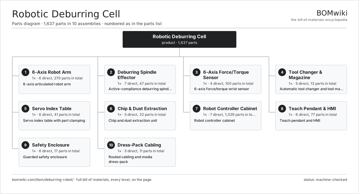
| # | Part | Qty | What it does |
|---|---|---|---|
| 1 | 6-Axis Robot Arm 6 parts | 1× | 6-axis articulated robot arm |
| 2 | Deburring Spindle Effector 7 parts | 1× | Active-compliance deburring spindle end-effector |
| 3 | 6-Axis Force/Torque Sensor 4 parts | 1× | 6-axis force/torque wrist sensor |
| 4 | Tool Changer & Magazine 5 parts | 1× | Automatic tool changer and tool magazine |
| 5 | Servo Index Table 6 parts | 1× | Servo index table with part clamping |
| 6 | Chip & Dust Extraction 5 parts | 1× | Chip and dust extraction unit |
| 7 | Robot Controller Cabinet 7 parts | 1× | Robot controller cabinet |
| 8 | Teach Pendant & HMI 6 parts | 1× | Teach pendant and HMI |
| 9 | Safety Enclosure 6 parts | 1× | Guarded safety enclosure |
| 10 | Dress-Pack Cabling 5 parts | 1× | Routed cabling and media dress-pack |
3D model
No 3D model yet. Have a CAD file of this? Add a 3D model — STL renders right on this page; STEP, FreeCAD, and OpenSCAD sources are welcome too (openly licensed, like all 3D models on BOMwiki).
Build & assembly graph
expand / collapse · shared sub-assemblies converge · links to related products · est. labourTap an assembly to expand/collapse · tap a part to open it · use “Open page” for any node · drag to pan, scroll to zoom.
Bill of materials for Robotic Deburring Cell
10 top-level lines · 117 rows shown · 1,637 parts total · indented to 3 levels| # | Item / sub-assembly | Part no. | Qty/assy | Ext. qty | Parts | Type |
|---|---|---|---|---|---|---|
| 1 | 6-Axis Robot Arm 6 parts | deburring-robot-arm | 1× | 1 | 270 | assembly |
| 1.1 | Robot Base Casting | deburring-robot-base | 1× | 1 | · | part |
| 1.2 | Servo Joint Module 7 parts | deburring-robot-joint | 6× | 6 | 41 | assembly |
| 1.2.1 | Servo Motor 4 parts + deeper › | servo-motor | 1× | 6 | 24 | assembly |
| 1.2.2 | Harmonic Drive Reducer 4 parts + deeper › | deburring-robot-harmonic-drive | 1× | 6 | 4 | assembly |
| 1.2.3 | RV Cycloidal Reducer 5 parts + deeper › | deburring-robot-rv-gearbox | 1× | 6 | 7 | assembly |
| 1.2.4 | Joint Absolute Encoder | deburring-robot-joint-encoder | 1× | 6 | · | part |
| 1.2.5 | Holding Brake | deburring-robot-joint-brake | 1× | 6 | · | part |
| 1.2.6 | Ball Bearing | ball-bearing | 2× | 12 | · | part |
| 1.2.7 | Oil Seal | oil-seal | 2× | 12 | · | part |
| 1.3 | Arm Link Casting | deburring-robot-link-casting | 5× | 5 | · | part |
| 1.4 | Counterbalance Cylinder | deburring-robot-counterbalance | 1× | 1 | · | part |
| 1.5 | Arm Internal Harness 2 parts | deburring-robot-arm-harness | 1× | 1 | 13 | assembly |
| 1.5.1 | Wire Bundle | wire-bundle | 1× | 1 | · | part |
| 1.5.2 | Connector | connector | 12× | 12 | · | part |
| 1.6 | Fastener Set | fastener-set | 4× | 4 | · | part |
| 2 | Deburring Spindle Effector 7 parts | deburring-robot-spindle-effector | 1× | 1 | 47 | assembly |
| 2.1 | High-Speed Spindle 5 parts | deburring-robot-spindle | 1× | 1 | 31 | assembly |
| 2.1.1 | Spindle Motor 3 parts + deeper › | deburring-robot-spindle-motor | 1× | 1 | 25 | assembly |
| 2.1.2 | Spindle Shaft | deburring-robot-spindle-shaft | 1× | 1 | · | part |
| 2.1.3 | Ball Bearing | ball-bearing | 3× | 3 | · | part |
| 2.1.4 | Spindle Housing | deburring-robot-spindle-housing | 1× | 1 | · | part |
| 2.1.5 | Oil Seal | oil-seal | 1× | 1 | · | part |
| 2.2 | Active Compliance Unit 5 parts | deburring-robot-compliance-unit | 1× | 1 | 6 | assembly |
| 2.2.1 | Float Piston | deburring-robot-float-piston | 1× | 1 | · | part |
| 2.2.2 | Coil Spring | coil-spring | 2× | 2 | · | part |
| 2.2.3 | Pressure Sensor | pressure-sensor | 1× | 1 | · | part |
| 2.2.4 | Proportional Pressure Valve | deburring-robot-proportional-valve | 1× | 1 | · | part |
| 2.2.5 | O-Ring Set | oring-set | 1× | 1 | · | part |
| 2.3 | ER Collet Chuck | deburring-robot-collet | 1× | 1 | · | part |
| 2.4 | Tungsten Carbide Burr | deburring-robot-carbide-burr | 4× | 4 | · | part |
| 2.5 | Abrasive Flap Wheel | deburring-robot-flap-wheel | 2× | 2 | · | part |
| 2.6 | Abrasive Filament Brush | deburring-robot-abrasive-brush | 2× | 2 | · | part |
| 2.7 | Effector Mount Flange | deburring-robot-effector-mount | 1× | 1 | · | part |
| 3 | 6-Axis Force/Torque Sensor 4 parts | deburring-robot-force-sensor | 1× | 1 | 100 | assembly |
| 3.1 | Sensor Flexure Element | deburring-robot-sensor-flexure | 1× | 1 | · | part |
| 3.2 | Strain Gauge | deburring-robot-strain-gauge | 6× | 6 | · | part |
| 3.3 | Sensor Amplifier Board 3 parts | deburring-robot-sensor-board | 1× | 1 | 92 | assembly |
| 3.3.1 | Bare PCB | pcb-bare | 1× | 1 | · | part |
| 3.3.2 | Microcontroller | mcu | 1× | 1 | · | part |
| 3.3.3 | SMD Passive (R/C/L) | smd-passives | 90× | 90 | · | part |
| 3.4 | Connector | connector | 1× | 1 | · | part |
| 4 | Tool Changer & Magazine 5 parts | deburring-robot-tool-changer | 1× | 1 | 13 | assembly |
| 4.1 | Master Coupling 3 parts | deburring-robot-changer-master | 1× | 1 | 3 | assembly |
| 4.1.1 | Lock Piston | deburring-robot-lock-piston | 1× | 1 | · | part |
| 4.1.2 | Locking Ball Set | deburring-robot-lock-balls | 1× | 1 | · | part |
| 4.1.3 | Connector | connector | 1× | 1 | · | part |
| 4.2 | Tool Coupling Plate | deburring-robot-changer-tool | 4× | 4 | · | part |
| 4.3 | Tool Parking Rack | deburring-robot-tool-rack | 1× | 1 | · | part |
| 4.4 | Tool Presence Switch | deburring-robot-presence-switch | 4× | 4 | · | part |
| 4.5 | O-Ring Set | oring-set | 1× | 1 | · | part |
| 5 | Servo Index Table 6 parts | deburring-robot-fixture-table | 1× | 1 | 41 | assembly |
| 5.1 | Rotary Table Top | deburring-robot-table-top | 1× | 1 | · | part |
| 5.2 | Index Drive 3 parts | deburring-robot-index-drive | 1× | 1 | 26 | assembly |
| 5.2.1 | Servo Motor 4 parts + deeper › | servo-motor | 1× | 1 | 24 | assembly |
| 5.2.2 | Helical Gear Pair | gear-pair | 1× | 1 | · | part |
| 5.2.3 | Joint Absolute Encoder | deburring-robot-joint-encoder | 1× | 1 | · | part |
| 5.3 | Clamping Fixture 3 parts | deburring-robot-clamp-fixture | 1× | 1 | 9 | assembly |
| 5.3.1 | Toggle Clamp | deburring-robot-toggle-clamp | 4× | 4 | · | part |
| 5.3.2 | Clamp Air Cylinder | deburring-robot-clamp-cylinder | 4× | 4 | · | part |
| 5.3.3 | O-Ring Set | oring-set | 1× | 1 | · | part |
| 5.4 | Locating Pin | deburring-robot-part-locator | 3× | 3 | · | part |
| 5.5 | Ball Bearing | ball-bearing | 1× | 1 | · | part |
| 5.6 | Part-Present Sensor | deburring-robot-part-present-sensor | 1× | 1 | · | part |
| 6 | Chip & Dust Extraction 5 parts | deburring-robot-extraction | 1× | 1 | 32 | assembly |
| 6.1 | Extraction Blower 3 parts | deburring-robot-extraction-fan | 1× | 1 | 27 | assembly |
| 6.1.1 | Servo Motor 4 parts + deeper › | servo-motor | 1× | 1 | 24 | assembly |
| 6.1.2 | Fan Impeller | deburring-robot-fan-impeller | 1× | 1 | · | part |
| 6.1.3 | Ball Bearing | ball-bearing | 2× | 2 | · | part |
| 6.2 | Cartridge Filter | deburring-robot-cartridge-filter | 2× | 2 | · | part |
| 6.3 | Capture Hood | deburring-robot-capture-hood | 1× | 1 | · | part |
| 6.4 | Spark Arrestor | deburring-robot-spark-arrestor | 1× | 1 | · | part |
| 6.5 | Extraction Duct | deburring-robot-extraction-duct | 1× | 1 | · | part |
| 7 | Robot Controller Cabinet 7 parts | deburring-robot-controller | 1× | 1 | 1,029 | assembly |
| 7.1 | Motion Control Computer 3 parts | deburring-robot-motion-cpu | 1× | 1 | 202 | assembly |
| 7.1.1 | Bare PCB | pcb-bare | 1× | 1 | · | part |
| 7.1.2 | Compute SoC Module | soc-module | 1× | 1 | · | part |
| 7.1.3 | SMD Passive (R/C/L) | smd-passives | 200× | 200 | · | part |
| 7.2 | Servo Drive 3 parts | deburring-robot-servo-drive | 6× | 6 | 122 | assembly |
| 7.2.1 | Bare PCB | pcb-bare | 1× | 6 | · | part |
| 7.2.2 | IGBT Power Module | igbt-module | 1× | 6 | · | part |
| 7.2.3 | SMD Passive (R/C/L) | smd-passives | 120× | 720 | · | part |
| 7.3 | Safety PLC 3 parts | deburring-robot-safety-plc | 1× | 1 | 83 | assembly |
| 7.3.1 | Bare PCB | pcb-bare | 1× | 1 | · | part |
| 7.3.2 | Microcontroller | mcu | 2× | 2 | · | part |
| 7.3.3 | SMD Passive (R/C/L) | smd-passives | 80× | 80 | · | part |
| 7.4 | Power Supply | power-supply | 1× | 1 | · | part |
| 7.5 | I/O Module | deburring-robot-io-module | 2× | 2 | · | part |
| 7.6 | Cabinet Cooling Unit | deburring-robot-cabinet-cooling | 1× | 1 | · | part |
| 7.7 | Relay | relay | 8× | 8 | · | part |
| 8 | Teach Pendant & HMI 6 parts | deburring-robot-pendant | 1× | 1 | 77 | assembly |
| 8.1 | LCD Panel | lcd-panel | 1× | 1 | · | part |
| 8.2 | Touch Digitizer | touch-digitizer | 1× | 1 | · | part |
| 8.3 | Enabling Switch | deburring-robot-enabling-switch | 1× | 1 | · | part |
| 8.4 | Pendant E-Stop | deburring-robot-pendant-estop | 1× | 1 | · | part |
| 8.5 | Pendant Logic Board 3 parts | deburring-robot-pendant-board | 1× | 1 | 72 | assembly |
| 8.5.1 | Bare PCB | pcb-bare | 1× | 1 | · | part |
| 8.5.2 | Microcontroller | mcu | 1× | 1 | · | part |
| 8.5.3 | SMD Passive (R/C/L) | smd-passives | 70× | 70 | · | part |
| 8.6 | Pendant Cable | deburring-robot-pendant-cable | 1× | 1 | · | part |
| 9 | Safety Enclosure 6 parts | deburring-robot-enclosure | 1× | 1 | 17 | assembly |
| 9.1 | Fence Panel | deburring-robot-fence-panel | 8× | 8 | · | part |
| 9.2 | Safety Light Curtain 2 parts | deburring-robot-light-curtain | 1× | 1 | 2 | assembly |
| 9.2.1 | Light Curtain Emitter | deburring-robot-curtain-emitter | 1× | 1 | · | part |
| 9.2.2 | Light Curtain Receiver | deburring-robot-curtain-receiver | 1× | 1 | · | part |
| 9.3 | Interlocked Access Door 2 parts | deburring-robot-safety-door | 1× | 1 | 2 | assembly |
| 9.3.1 | Guard-Locking Interlock | deburring-robot-door-interlock | 1× | 1 | · | part |
| 9.3.2 | Sheet Metal Panel | sheet-panel | 1× | 1 | · | part |
| 9.4 | E-Stop Station | deburring-robot-estop-station | 2× | 2 | · | part |
| 9.5 | Status Beacon | deburring-robot-status-beacon | 1× | 1 | · | part |
| 9.6 | Fastener Set | fastener-set | 2× | 2 | · | part |
| 10 | Dress-Pack Cabling 5 parts | deburring-robot-dress-pack | 1× | 1 | 11 | assembly |
| 10.1 | Wire Bundle | wire-bundle | 1× | 1 | · | part |
| 10.2 | Air Hose | deburring-robot-air-hose | 2× | 2 | · | part |
| 10.3 | Cable Carrier | deburring-robot-cable-carrier | 1× | 1 | · | part |
| 10.4 | Rotary Union | deburring-robot-rotary-union | 1× | 1 | · | part |
| 10.5 | Connector | connector | 6× | 6 | · | part |
Related products
same domain, ranked by shared parts Robotic Assembly Cell
1,746 parts · shares 12 with this page
Sealant Dispensing Robot
2,056 parts · shares 11 with this page
Robotic Grinding Cell
1,419 parts · shares 11 with this page
Robotic Screwdriving Cell
2,109 parts · shares 11 with this page
Robotic Sanding Cell
1,464 parts · shares 10 with this page
Robotic Bartender Cell
493 parts · shares 9 with this page
Robotic Assembly Cell
1,746 parts · shares 12 with this page
Sealant Dispensing Robot
2,056 parts · shares 11 with this page
Robotic Grinding Cell
1,419 parts · shares 11 with this page
Robotic Screwdriving Cell
2,109 parts · shares 11 with this page
Robotic Sanding Cell
1,464 parts · shares 10 with this page
Robotic Bartender Cell
493 parts · shares 9 with this page
Sourcing: possible vendors
Prices, MOQ, and lead times are algorithmic estimates, not quotes, and not claims about these companies. Company mappings are curated by keyword; est. price band $3k–$500k. How estimates work| Vendor | HQ | Specialty | MOQ | Lead time |
|---|---|---|---|---|
|
🇯🇵Fanuc
fanuc.com ↗
|
Oshino, JP | Industrial robots & CNC | 20 units | 10–18 wks |
| abb.com ↗ | Zurich, CH | Industrial robots | 20 units | 10–18 wks |
|
🇯🇵Yaskawa
yaskawa.com ↗
|
Kitakyushu, JP | Robots & motion | 20 units | 10–18 wks |
|
🇩🇪KUKA
kuka.com ↗
|
Augsburg, DE | Industrial robots | 20 units | 10–18 wks |
| universal-robots.com ↗ | Odense, DK | Collaborative robots | 20 units | 10–18 wks |
1,206-word article