Robotic Grinding Cell
ProductOverview
A robotic grinding cell replaces manual bench grinding with a 6-Axis Robot Arm that holds an abrasive tool and moves it across a workpiece along a programmed path. Manual grinding is slow, inconsistent between operators, and exposes workers to dust, sparks, and vibration. A robot grinds the same way on every part, runs for full shifts, and keeps people out of the hazard zone behind a Safety Enclosure. The cell is used to deburr castings, blend weld seams, finish turbine blades, and put a uniform surface on forgings and fabricated parts.
The cell has ten major subsystems. The 6-Axis Robot Arm positions and orients the tool. The Grinding End-Effector carries the Grinding Spindle and abrasive media. The Active Force-Control Unit holds a constant contact pressure as the part shape changes. The Wheel Dressing Station re-cuts the wheel when it loads up. The Part Fixture and Index Table clamps and indexes the part. The Swarf and Dust Extraction pulls away dust and sparks. The Robot Controller runs the motion, and the Teach Pendant is how a technician programs and jogs the robot. The Dress-Pack Cabling carries power, signal, and air out to the tool.
How it works
The robot reaches a point in space using six rotary axes. Each axis is a Axis Servo Drive: a Servo Motor feeding a Harmonic Drive Reducer that gives a high reduction ratio with almost no backlash, plus a Axis Absolute Encoder on the joint output that resolves position to arc-seconds. The first three axes set the wrist position; the last three, packed into the Wrist Housing, set the tool orientation. A Axis Holding Brake on each joint locks the arm in place when power drops so the heavy tool does not fall.
Holding position is not enough for grinding. The abrasive removes material, so the gap between tool and part keeps changing, and a position-only robot would either dig in or lose contact. The Active Force-Control Unit solves this. A Force/Torque Sensor measures the contact force, and a Force-Control Board drives a Proportional Regulator feeding a Compliance Actuator so the tool floats against the part at a commanded force, anywhere from 5 to 250 N. The robot follows the nominal path, and the compliance unit absorbs the difference between the programmed path and the real surface.
Grinding media
The Grinding End-Effector carries two kinds of media. The Grinding Spindle runs a 200 mm Abrasive Grinding Wheel for stock removal and edge work, mounted between relieved Wheel Flange halves and spun by a Spindle Motor at up to 24,000 rpm on angular-contact Ball Bearing pairs. For finishing and seam blending, a Belt Grinder Module module runs a Abrasive Belt over a rubber-faced Contact Wheel, driven through a Drive Belt and kept taut by a Belt Tensioner with a Coil Spring and tracked by two Idler Wheel units. The whole tool clamps to the wrist through an ISO 9409 Tool Flange so it can be swapped.
Wheel dressing
A grinding wheel dulls and clogs in use. The Wheel Dressing Station restores it. The robot presents the wheel to a spinning Diamond Dressing Roll carried on a Dresser Spindle, and a Dresser Infeed Slide ball-screw slide advances the roll into the wheel in micron steps. Dressing trues the wheel profile and exposes fresh abrasive, which keeps the surface finish and removal rate stable across a long run.
Fixturing and extraction
The Part Fixture and Index Table is a servo Index Drive turning a Rotary Platen. A Clamp Fixture with pneumatic Clamp Cylinder units and hardened Locating Pin features locates the part repeatably, and the table indexes to present new faces without an operator reaching in. Grinding throws off fine dust and hot sparks, so a Extraction Blower pulls the work-zone air through a cyclonic Spark Arrestor that cools and drops the sparks, then through a Filter Cartridge pair before the air is returned. Captured swarf collects in a Swarf Bin.
Control and safety
The Robot Controller cabinet holds a Motion Computer, six Servo Amplifier units, and a dual-channel Safety PLC. A technician programs the cell from the Teach Pendant, jogging the arm with a Enabling Switch held at its middle detent. Safety is built around keeping people clear of a fast, sharp tool. The Safety Enclosure fences the work envelope, a Safety Light Curtain stops motion if anyone breaks the entrance plane, the Access Door carries a guard-locking Door Interlock, and E-Stop Station buttons sit at every access point.
Materials and abrasive choice
The abrasive is matched to the workpiece. A vitrified aluminum oxide Abrasive Grinding Wheel suits carbon and alloy steels and is cheap to replace, while a cubic boron nitride wheel holds its profile far longer on hardened steel and is reserved for high-volume runs where the dressing interval matters. Castings in gray iron or aluminum are usually blended with a coated Abrasive Belt in 36 to 120 grit, stepping from coarse stock removal to a finer finishing pass on the same Belt Grinder Module head. The Contact Wheel durometer is selected alongside the belt: a hard 70 to 90 Shore A wheel cuts aggressively on flats, and a soft 30 to 40 Shore A wheel conforms to radii and fillets without gouging.
Structural parts of the cell are chosen for stiffness and wear. The 6-Axis Robot Arm links and Wrist Housing are cast aluminum to keep the moving mass low, while the Part Fixture and Index Table platen and the Clamp Fixture are steel so they hold tolerance under repeated clamping loads. The Locating Pin features are hardened and ground to survive thousands of part loads without losing position. Wetted and high-wear surfaces in the Swarf and Dust Extraction path, including the Spark Arrestor cone, use abrasion-resistant liners because the swarf is hot and sharp.
Variants and use
Cells are sized to the work. A small cell with an 1,800 mm reach and a 20 kg payload deburrs die castings and small forgings, while a large cell with a 2,600 mm reach and a 35 kg payload handles pump casings, valve bodies, and structural weldments. Foundries run grinding cells to remove gates, risers, and parting-line flash from castings as they come off the line. Fabrication shops use them to blend welds flush and to break sharp edges on plate parts. Aerospace shops grind and polish turbine blades and blisks where a uniform, repeatable finish drives fatigue life. In every case the value is the same: the Active Force-Control Unit and Robot Controller together hold a consistent removal rate and surface finish that a hand grinder cannot match across a full shift.
Robotic Grinding Cell parts and their functions
10 top-level parts · 1,419 parts in total · full bill of materials below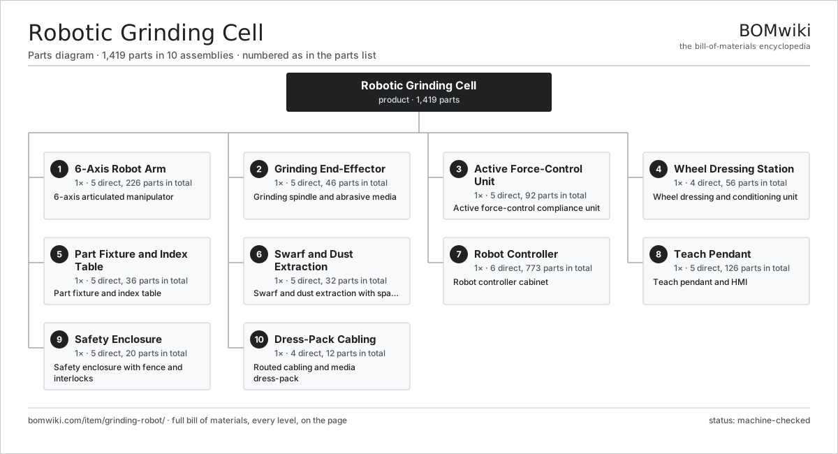
| # | Part | Qty | What it does |
|---|---|---|---|
| 1 | 6-Axis Robot Arm 5 parts | 1× | 6-axis articulated manipulator |
| 2 | Grinding End-Effector 5 parts | 1× | Grinding spindle and abrasive media |
| 3 | Active Force-Control Unit 5 parts | 1× | Active force-control compliance unit |
| 4 | Wheel Dressing Station 4 parts | 1× | Wheel dressing and conditioning unit |
| 5 | Part Fixture and Index Table 5 parts | 1× | Part fixture and index table |
| 6 | Swarf and Dust Extraction 5 parts | 1× | Swarf and dust extraction with spark arrestor |
| 7 | Robot Controller 6 parts | 1× | Robot controller cabinet |
| 8 | Teach Pendant 5 parts | 1× | Teach pendant and HMI |
| 9 | Safety Enclosure 5 parts | 1× | Safety enclosure with fence and interlocks |
| 10 | Dress-Pack Cabling 4 parts | 1× | Routed cabling and media dress-pack |
3D model
No 3D model yet. Have a CAD file of this? Add a 3D model — STL renders right on this page; STEP, FreeCAD, and OpenSCAD sources are welcome too (openly licensed, like all 3D models on BOMwiki).
Build & assembly graph
expand / collapse · shared sub-assemblies converge · links to related products · est. labourTap an assembly to expand/collapse · tap a part to open it · use “Open page” for any node · drag to pan, scroll to zoom.
Bill of materials for Robotic Grinding Cell
10 top-level lines · 125 rows shown · 1,419 parts total · indented to 3 levels| # | Item / sub-assembly | Part no. | Qty/assy | Ext. qty | Parts | Type |
|---|---|---|---|---|---|---|
| 1 | 6-Axis Robot Arm 5 parts | grinding-robot-arm | 1× | 1 | 226 | assembly |
| 1.1 | Arm Base Casting 3 parts | grinding-robot-base | 1× | 1 | 3 | assembly |
| 1.1.1 | Base Casting | grinding-robot-base-casting | 1× | 1 | · | part |
| 1.1.2 | Ball Bearing | ball-bearing | 1× | 1 | · | part |
| 1.1.3 | Fastener Set | fastener-set | 1× | 1 | · | part |
| 1.2 | Axis Servo Drive 5 parts | grinding-robot-axis-drive | 6× | 6 | 32 | assembly |
| 1.2.1 | Servo Motor 4 parts + deeper › | servo-motor | 1× | 6 | 24 | assembly |
| 1.2.2 | Harmonic Drive Reducer 4 parts + deeper › | grinding-robot-harmonic-drive | 1× | 6 | 4 | assembly |
| 1.2.3 | Axis Absolute Encoder | grinding-robot-axis-encoder | 1× | 6 | · | part |
| 1.2.4 | Axis Holding Brake | grinding-robot-axis-brake | 1× | 6 | · | part |
| 1.2.5 | Ball Bearing | ball-bearing | 2× | 12 | · | part |
| 1.3 | Link and Wrist Castings 4 parts | grinding-robot-link-set | 1× | 1 | 4 | assembly |
| 1.3.1 | Lower Arm Casting | grinding-robot-lower-arm | 1× | 1 | · | part |
| 1.3.2 | Upper Arm Casting | grinding-robot-upper-arm | 1× | 1 | · | part |
| 1.3.3 | Wrist Housing | grinding-robot-wrist-housing | 1× | 1 | · | part |
| 1.3.4 | Fastener Set | fastener-set | 1× | 1 | · | part |
| 1.4 | Arm Internal Harness 2 parts | grinding-robot-arm-harness | 1× | 1 | 15 | assembly |
| 1.4.1 | Wire Bundle | wire-bundle | 1× | 1 | · | part |
| 1.4.2 | Connector | connector | 14× | 14 | · | part |
| 1.5 | Oil Seal | oil-seal | 12× | 12 | · | part |
| 2 | Grinding End-Effector 5 parts | grinding-robot-endeffector | 1× | 1 | 46 | assembly |
| 2.1 | Grinding Spindle 5 parts | grinding-robot-spindle | 1× | 1 | 31 | assembly |
| 2.1.1 | Spindle Motor 3 parts + deeper › | grinding-robot-spindle-motor | 1× | 1 | 23 | assembly |
| 2.1.2 | Spindle Shaft | grinding-robot-spindle-shaft | 1× | 1 | · | part |
| 2.1.3 | Ball Bearing | ball-bearing | 4× | 4 | · | part |
| 2.1.4 | Wheel Flange | grinding-robot-wheel-flange | 1× | 1 | · | part |
| 2.1.5 | Oil Seal | oil-seal | 2× | 2 | · | part |
| 2.2 | Abrasive Grinding Wheel | grinding-robot-abrasive-wheel | 1× | 1 | · | part |
| 2.3 | Belt Grinder Module 6 parts | grinding-robot-belt-grinder | 1× | 1 | 12 | assembly |
| 2.3.1 | Contact Wheel | grinding-robot-contact-wheel | 1× | 1 | · | part |
| 2.3.2 | Abrasive Belt | grinding-robot-abrasive-belt | 1× | 1 | · | part |
| 2.3.3 | Belt Tensioner 3 parts + deeper › | grinding-robot-belt-tensioner | 1× | 1 | 3 | assembly |
| 2.3.4 | Idler Wheel | grinding-robot-idler-wheel | 2× | 2 | · | part |
| 2.3.5 | Drive Belt | drive-belt | 1× | 1 | · | part |
| 2.3.6 | Ball Bearing | ball-bearing | 4× | 4 | · | part |
| 2.4 | Tool Flange | grinding-robot-tool-flange | 1× | 1 | · | part |
| 2.5 | Wheel Guard | grinding-robot-guard | 1× | 1 | · | part |
| 3 | Active Force-Control Unit 5 parts | grinding-robot-force-control | 1× | 1 | 92 | assembly |
| 3.1 | Compliance Actuator 3 parts | grinding-robot-compliance-actuator | 1× | 1 | 3 | assembly |
| 3.1.1 | Pneumatic Cylinder | grinding-robot-pneu-cylinder | 1× | 1 | · | part |
| 3.1.2 | O-Ring Set | oring-set | 1× | 1 | · | part |
| 3.1.3 | Linear Guide Rail | linear-guide | 1× | 1 | · | part |
| 3.2 | Force/Torque Sensor | grinding-robot-force-sensor | 1× | 1 | · | part |
| 3.3 | Proportional Regulator | grinding-robot-pressure-regulator | 1× | 1 | · | part |
| 3.4 | Pressure Sensor | pressure-sensor | 1× | 1 | · | part |
| 3.5 | Force-Control Board 4 parts | grinding-robot-fc-controller | 1× | 1 | 86 | assembly |
| 3.5.1 | Bare PCB | pcb-bare | 1× | 1 | · | part |
| 3.5.2 | Microcontroller | mcu | 1× | 1 | · | part |
| 3.5.3 | SMD Passive (R/C/L) | smd-passives | 80× | 80 | · | part |
| 3.5.4 | Connector | connector | 4× | 4 | · | part |
| 4 | Wheel Dressing Station 4 parts | grinding-robot-dressing-station | 1× | 1 | 56 | assembly |
| 4.1 | Dresser Spindle 3 parts | grinding-robot-dresser-spindle | 1× | 1 | 27 | assembly |
| 4.1.1 | Servo Motor 4 parts + deeper › | servo-motor | 1× | 1 | 24 | assembly |
| 4.1.2 | Ball Bearing | ball-bearing | 2× | 2 | · | part |
| 4.1.3 | Oil Seal | oil-seal | 1× | 1 | · | part |
| 4.2 | Diamond Dressing Roll | grinding-robot-diamond-roll | 1× | 1 | · | part |
| 4.3 | Dresser Infeed Slide 3 parts | grinding-robot-dresser-feed | 1× | 1 | 27 | assembly |
| 4.3.1 | Ball Screw | ball-screw | 1× | 1 | · | part |
| 4.3.2 | Linear Guide Rail | linear-guide | 2× | 2 | · | part |
| 4.3.3 | Servo Motor 4 parts + deeper › | servo-motor | 1× | 1 | 24 | assembly |
| 4.4 | Dressing Station Base | grinding-robot-dresser-base | 1× | 1 | · | part |
| 5 | Part Fixture and Index Table 5 parts | grinding-robot-fixture-table | 1× | 1 | 36 | assembly |
| 5.1 | Index Drive 4 parts | grinding-robot-index-drive | 1× | 1 | 27 | assembly |
| 5.1.1 | Servo Motor 4 parts + deeper › | servo-motor | 1× | 1 | 24 | assembly |
| 5.1.2 | Gearbox Housing | gearbox-housing | 1× | 1 | · | part |
| 5.1.3 | Helical Gear Pair | gear-pair | 1× | 1 | · | part |
| 5.1.4 | Oil Seal | oil-seal | 1× | 1 | · | part |
| 5.2 | Rotary Platen | grinding-robot-table-platen | 1× | 1 | · | part |
| 5.3 | Clamp Fixture 3 parts | grinding-robot-clamp-fixture | 1× | 1 | 6 | assembly |
| 5.3.1 | Clamp Cylinder | grinding-robot-clamp-cylinder | 2× | 2 | · | part |
| 5.3.2 | Locating Pin | grinding-robot-locating-pin | 3× | 3 | · | part |
| 5.3.3 | O-Ring Set | oring-set | 1× | 1 | · | part |
| 5.4 | Ball Bearing | ball-bearing | 1× | 1 | · | part |
| 5.5 | Table Base | grinding-robot-table-base | 1× | 1 | · | part |
| 6 | Swarf and Dust Extraction 5 parts | grinding-robot-extraction | 1× | 1 | 32 | assembly |
| 6.1 | Extraction Blower 3 parts | grinding-robot-extract-blower | 1× | 1 | 27 | assembly |
| 6.1.1 | Servo Motor 4 parts + deeper › | servo-motor | 1× | 1 | 24 | assembly |
| 6.1.2 | Blower Impeller | grinding-robot-impeller | 1× | 1 | · | part |
| 6.1.3 | Ball Bearing | ball-bearing | 2× | 2 | · | part |
| 6.2 | Spark Arrestor | grinding-robot-spark-arrestor | 1× | 1 | · | part |
| 6.3 | Filter Cartridge | grinding-robot-filter-cartridge | 2× | 2 | · | part |
| 6.4 | Extraction Ductwork | grinding-robot-ductwork | 1× | 1 | · | part |
| 6.5 | Swarf Bin | grinding-robot-swarf-bin | 1× | 1 | · | part |
| 7 | Robot Controller 6 parts | grinding-robot-controller | 1× | 1 | 773 | assembly |
| 7.1 | Motion Computer 4 parts | grinding-robot-motion-cpu | 1× | 1 | 210 | assembly |
| 7.1.1 | Bare PCB | pcb-bare | 1× | 1 | · | part |
| 7.1.2 | Compute SoC Module | soc-module | 1× | 1 | · | part |
| 7.1.3 | SMD Passive (R/C/L) | smd-passives | 200× | 200 | · | part |
| 7.1.4 | Connector | connector | 8× | 8 | · | part |
| 7.2 | Servo Amplifier 3 parts | grinding-robot-servo-amp | 6× | 6 | 92 | assembly |
| 7.2.1 | Bare PCB | pcb-bare | 1× | 6 | · | part |
| 7.2.2 | IGBT Power Module | igbt-module | 1× | 6 | · | part |
| 7.2.3 | SMD Passive (R/C/L) | smd-passives | 90× | 540 | · | part |
| 7.3 | Safety PLC 3 parts | grinding-robot-safety-plc | 1× | 1 | 7 | assembly |
| 7.3.1 | Bare PCB | pcb-bare | 1× | 1 | · | part |
| 7.3.2 | Microcontroller | mcu | 2× | 2 | · | part |
| 7.3.3 | Relay | relay | 4× | 4 | · | part |
| 7.4 | Power Supply | power-supply | 1× | 1 | · | part |
| 7.5 | Controller Cabinet | grinding-robot-cabinet | 1× | 1 | · | part |
| 7.6 | I/O Module | grinding-robot-io-module | 2× | 2 | · | part |
| 8 | Teach Pendant 5 parts | grinding-robot-pendant | 1× | 1 | 126 | assembly |
| 8.1 | LCD Panel | lcd-panel | 1× | 1 | · | part |
| 8.2 | Touch Digitizer | touch-digitizer | 1× | 1 | · | part |
| 8.3 | Pendant Mainboard 3 parts | grinding-robot-pendant-board | 1× | 1 | 122 | assembly |
| 8.3.1 | Bare PCB | pcb-bare | 1× | 1 | · | part |
| 8.3.2 | Compute SoC Module | soc-module | 1× | 1 | · | part |
| 8.3.3 | SMD Passive (R/C/L) | smd-passives | 120× | 120 | · | part |
| 8.4 | Enabling Switch | grinding-robot-enable-switch | 1× | 1 | · | part |
| 8.5 | E-Stop Button | grinding-robot-estop-button | 1× | 1 | · | part |
| 9 | Safety Enclosure 5 parts | grinding-robot-enclosure | 1× | 1 | 20 | assembly |
| 9.1 | Fence Panel | grinding-robot-fence-panel | 8× | 8 | · | part |
| 9.2 | Safety Light Curtain 3 parts | grinding-robot-light-curtain | 1× | 1 | 4 | assembly |
| 9.2.1 | Light Curtain Emitter | grinding-robot-lc-emitter | 1× | 1 | · | part |
| 9.2.2 | Light Curtain Receiver | grinding-robot-lc-receiver | 1× | 1 | · | part |
| 9.2.3 | Connector | connector | 2× | 2 | · | part |
| 9.3 | Access Door 2 parts | grinding-robot-access-door | 1× | 1 | 2 | assembly |
| 9.3.1 | Door Frame | grinding-robot-door-frame | 1× | 1 | · | part |
| 9.3.2 | Door Interlock | grinding-robot-door-interlock | 1× | 1 | · | part |
| 9.4 | E-Stop Station | grinding-robot-estop-station | 2× | 2 | · | part |
| 9.5 | Sheet Metal Panel | sheet-panel | 4× | 4 | · | part |
| 10 | Dress-Pack Cabling 4 parts | grinding-robot-dress-pack | 1× | 1 | 12 | assembly |
| 10.1 | Wire Bundle | wire-bundle | 1× | 1 | · | part |
| 10.2 | Air Hose | grinding-robot-air-hose | 2× | 2 | · | part |
| 10.3 | Cable Carrier | grinding-robot-cable-carrier | 1× | 1 | · | part |
| 10.4 | Connector | connector | 8× | 8 | · | part |
Related products
same domain, ranked by shared parts Robotic Assembly Cell
1,746 parts · shares 14 with this page
Robotic Screwdriving Cell
2,109 parts · shares 12 with this page
Robotic Sanding Cell
1,464 parts · shares 11 with this page
Robotic Palletizing Cell
986 parts · shares 10 with this page
Robotic Deburring Cell
1,637 parts · shares 11 with this page
Sealant Dispensing Robot
2,056 parts · shares 10 with this page
Robotic Assembly Cell
1,746 parts · shares 14 with this page
Robotic Screwdriving Cell
2,109 parts · shares 12 with this page
Robotic Sanding Cell
1,464 parts · shares 11 with this page
Robotic Palletizing Cell
986 parts · shares 10 with this page
Robotic Deburring Cell
1,637 parts · shares 11 with this page
Sealant Dispensing Robot
2,056 parts · shares 10 with this page
Sourcing: possible vendors
Prices, MOQ, and lead times are algorithmic estimates, not quotes, and not claims about these companies. Company mappings are curated by keyword; est. price band $3k–$500k. How estimates work| Vendor | HQ | Specialty | MOQ | Lead time |
|---|---|---|---|---|
|
🇯🇵Fanuc
fanuc.com ↗
|
Oshino, JP | Industrial robots & CNC | 20 units | 10–18 wks |
| abb.com ↗ | Zurich, CH | Industrial robots | 20 units | 10–18 wks |
|
🇯🇵Yaskawa
yaskawa.com ↗
|
Kitakyushu, JP | Robots & motion | 20 units | 10–18 wks |
|
🇩🇪KUKA
kuka.com ↗
|
Augsburg, DE | Industrial robots | 20 units | 10–18 wks |
| universal-robots.com ↗ | Odense, DK | Collaborative robots | 20 units | 10–18 wks |
1,208-word article