Seven-Axis Industrial Robot
ProductOverview
A seven-axis industrial robot is a conventional six-axis arm with one extra joint added in the middle. That sounds like a small change, but it removes a frustration that limits ordinary robots. A six-axis arm has exactly enough joints to put its tool at any position and orientation, and no spare freedom, so for any given tool pose the arm has essentially one posture. If that posture means the elbow has to swing through a fixture, a wall, or the part itself, the robot simply cannot reach. A seventh axis gives the arm a redundant degree of freedom: it can hold the tool perfectly still and still move its elbow, swinging it around an obstacle or folding the whole arm into a tighter envelope. This is why seven-axis arms are used to reach inside machines, around car bodies, and into crowded cells where a six-axis robot would collide with its surroundings.
How it works
Like a six-axis robot, this arm is a chain of rotary joints, but it has seven rather than six. Every axis is built from the same Servo Joint Module module so the design is consistent and serviceable: a Servo Motor driving a RV Reducer cycloidal reducer, held by a Holding Brake when power is off, and read by two encoders. The dual feedback matters: a Motor-Side Encoder on the motor handles commutation while a Output-Side Encoder after the reducer reports the true joint angle, which lets the controller correct for the small flex and lost motion in the gearing. The cycloidal reducer is chosen across all axes because it is stiff and tolerates the shock loads of industrial work.
The arm starts at the Base Joint that rotates the whole machine about the vertical. Above it the Shoulder Section carries the two big lift axes that raise and reach the upper arm, the most heavily loaded joints because they swing the entire weight beyond them. Then comes the part that makes this robot a seven-axis: the Redundant Elbow, a roll axis inserted between the shoulder and the wrist. This is the redundant joint. Finally the Three-Axis Wrist supplies the last three axes, pitch, yaw, and roll of the tool, ending in a Tool Flange that carries the gripper or process tool and its I/O.
The redundant axis
The value of the seventh axis is best understood through what the controller does with it. With six axes, asking for a tool pose gives one answer for the joint angles. With seven, there is a whole family of answers: an extra dimension of postures that all put the tool in the same place. The Robot Controller uses that freedom to choose, in real time, an elbow position that avoids collisions, keeps every joint away from its limits, and improves the arm's stiffness for the task. As the tool traces a path, the elbow can sweep continuously to one side to clear a fixture without the tool ever wavering. The same freedom lets the arm reconfigure on the fly when a joint approaches its travel limit, which on a six-axis robot would force an awkward retreat and re-approach.
Structure and links
The joints are tied together by the cast Arm Link Set. These castings are sized for stiffness because any flex in the structure shows up directly as tool error at the far end of a 1.4 metre reach. The shoulder and base castings are the heaviest, carrying the bending loads of the extended arm, while the links toward the wrist are lighter since they support less beyond them. Routing cables through a seven-joint arm is harder than through six, so the Internal Cabling runs through hollow joints and a Cable Carrier where it must cross the moving structure, kept clear of the extra elbow motion.
Control and programming
The Robot Controller runs a Servo Drive for each of the seven motors and enforces speed and zone limits through a redundant Safety Board. Its Controller Main Board does the heavier kinematic work that the extra axis demands, since resolving the redundancy is more involved than the closed-form solution a six-axis arm allows. An operator programs the robot from the Teach Pendant, jogging it and teaching points, and the controller can also accept programs generated offline from a CAD model of the cell, which is common for the complex paths these arms are bought to run.
Materials and variants
The castings are iron and aluminium, the reducer internals alloy steel running in grease or oil, and the wrist is sealed to a high IP rating because these arms often work in welding, painting, and washdown environments. Seven-axis arms are sold across the same payload range as six-axis models, from small assembly units up to heavy handling, with the redundant axis added to each size. Some variants place the extra joint differently, at the shoulder rather than the elbow, trading one kind of dexterity for another, and collaborative seven-axis arms add joint torque sensing so they can also work next to people.
Use
Seven-axis robots earn their extra cost wherever reach is constrained: tending machine tools through narrow doors, welding and sealing inside car bodies, painting around complex shapes, and packing into deep or crowded spaces. They are also used where one robot must serve several stations from a fixed base, since the redundant axis lets it fold and twist to reach them all. The trade is complexity, an extra motor, drive, and reducer to buy and maintain, justified when a six-axis arm simply cannot get where the work is.
Seven-Axis Industrial Robot parts and their functions
7 top-level parts · 1,450 parts in total · full bill of materials below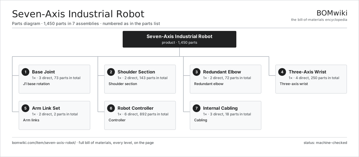
| # | Part | Qty | What it does |
|---|---|---|---|
| 1 | Base Joint 3 parts | 1× | J1 base rotation |
| 2 | Shoulder Section 2 parts | 1× | Shoulder section |
| 3 | Redundant Elbow 2 parts | 1× | Redundant elbow |
| 4 | Three-Axis Wrist 4 parts | 1× | Three-axis wrist |
| 5 | Arm Link Set 2 parts | 1× | Arm links |
| 6 | Robot Controller 6 parts | 1× | Controller |
| 7 | Internal Cabling 3 parts | 1× | Cabling |
3D model
No 3D model yet. Have a CAD file of this? Add a 3D model — STL renders right on this page; STEP, FreeCAD, and OpenSCAD sources are welcome too (openly licensed, like all 3D models on BOMwiki).
Build & assembly graph
expand / collapse · shared sub-assemblies converge · links to related products · est. labourTap an assembly to expand/collapse · tap a part to open it · use “Open page” for any node · drag to pan, scroll to zoom.
Bill of materials for Seven-Axis Industrial Robot
7 top-level lines · 72 rows shown · 1,450 parts total · indented to 3 levels| # | Item / sub-assembly | Part no. | Qty/assy | Ext. qty | Parts | Type |
|---|---|---|---|---|---|---|
| 1 | Base Joint 3 parts | seven-axis-robot-base-joint | 1× | 1 | 73 | assembly |
| 1.1 | Servo Joint Module 6 parts | seven-axis-robot-joint | 1× | 1 | 71 | assembly |
| 1.1.1 | Servo Motor 4 parts + deeper › | servo-motor | 1× | 1 | 24 | assembly |
| 1.1.2 | RV Reducer 4 parts + deeper › | seven-axis-robot-reducer | 1× | 1 | 6 | assembly |
| 1.1.3 | Holding Brake | seven-axis-robot-brake | 1× | 1 | · | part |
| 1.1.4 | Motor-Side Encoder 2 parts + deeper › | seven-axis-robot-motor-encoder | 1× | 1 | 19 | assembly |
| 1.1.5 | Output-Side Encoder 2 parts + deeper › | seven-axis-robot-output-encoder | 1× | 1 | 19 | assembly |
| 1.1.6 | Ball Bearing | ball-bearing | 2× | 2 | · | part |
| 1.2 | Base Casting | seven-axis-robot-base-casting | 1× | 1 | · | part |
| 1.3 | Fastener Set | fastener-set | 1× | 1 | · | part |
| 2 | Shoulder Section 2 parts | seven-axis-robot-shoulder | 1× | 1 | 143 | assembly |
| 2.1 | Servo Joint Module 6 parts | seven-axis-robot-joint | 2× | 2 | 71 | assembly |
| 2.1.1 | Servo Motor 4 parts + deeper › | servo-motor | 1× | 2 | 24 | assembly |
| 2.1.2 | RV Reducer 4 parts + deeper › | seven-axis-robot-reducer | 1× | 2 | 6 | assembly |
| 2.1.3 | Holding Brake | seven-axis-robot-brake | 1× | 2 | · | part |
| 2.1.4 | Motor-Side Encoder 2 parts + deeper › | seven-axis-robot-motor-encoder | 1× | 2 | 19 | assembly |
| 2.1.5 | Output-Side Encoder 2 parts + deeper › | seven-axis-robot-output-encoder | 1× | 2 | 19 | assembly |
| 2.1.6 | Ball Bearing | ball-bearing | 2× | 4 | · | part |
| 2.2 | Shoulder Casting | seven-axis-robot-shoulder-casting | 1× | 1 | · | part |
| 3 | Redundant Elbow 2 parts | seven-axis-robot-elbow | 1× | 1 | 72 | assembly |
| 3.1 | Servo Joint Module 6 parts | seven-axis-robot-joint | 1× | 1 | 71 | assembly |
| 3.1.1 | Servo Motor 4 parts + deeper › | servo-motor | 1× | 1 | 24 | assembly |
| 3.1.2 | RV Reducer 4 parts + deeper › | seven-axis-robot-reducer | 1× | 1 | 6 | assembly |
| 3.1.3 | Holding Brake | seven-axis-robot-brake | 1× | 1 | · | part |
| 3.1.4 | Motor-Side Encoder 2 parts + deeper › | seven-axis-robot-motor-encoder | 1× | 1 | 19 | assembly |
| 3.1.5 | Output-Side Encoder 2 parts + deeper › | seven-axis-robot-output-encoder | 1× | 1 | 19 | assembly |
| 3.1.6 | Ball Bearing | ball-bearing | 2× | 2 | · | part |
| 3.2 | Elbow Casting | seven-axis-robot-elbow-casting | 1× | 1 | · | part |
| 4 | Three-Axis Wrist 4 parts | seven-axis-robot-wrist | 1× | 1 | 250 | assembly |
| 4.1 | Servo Joint Module 6 parts | seven-axis-robot-joint | 3× | 3 | 71 | assembly |
| 4.1.1 | Servo Motor 4 parts + deeper › | servo-motor | 1× | 3 | 24 | assembly |
| 4.1.2 | RV Reducer 4 parts + deeper › | seven-axis-robot-reducer | 1× | 3 | 6 | assembly |
| 4.1.3 | Holding Brake | seven-axis-robot-brake | 1× | 3 | · | part |
| 4.1.4 | Motor-Side Encoder 2 parts + deeper › | seven-axis-robot-motor-encoder | 1× | 3 | 19 | assembly |
| 4.1.5 | Output-Side Encoder 2 parts + deeper › | seven-axis-robot-output-encoder | 1× | 3 | 19 | assembly |
| 4.1.6 | Ball Bearing | ball-bearing | 2× | 6 | · | part |
| 4.2 | Wrist Housing | seven-axis-robot-wrist-housing | 1× | 1 | · | part |
| 4.3 | Tool Flange 2 parts | seven-axis-robot-tool-flange | 1× | 1 | 34 | assembly |
| 4.3.1 | Flange Plate | seven-axis-robot-flange-plate | 1× | 1 | · | part |
| 4.3.2 | Tool I/O Board 3 parts + deeper › | seven-axis-robot-tool-io | 1× | 1 | 33 | assembly |
| 4.4 | Helical Gear Pair | gear-pair | 2× | 2 | · | part |
| 5 | Arm Link Set 2 parts | seven-axis-robot-link-set | 1× | 1 | 2 | assembly |
| 5.1 | Lower Arm Casting | seven-axis-robot-lower-arm | 1× | 1 | · | part |
| 5.2 | Upper Arm Casting | seven-axis-robot-upper-arm | 1× | 1 | · | part |
| 6 | Robot Controller 6 parts | seven-axis-robot-controller | 1× | 1 | 892 | assembly |
| 6.1 | Controller Main Board 4 parts | seven-axis-robot-main-board | 1× | 1 | 235 | assembly |
| 6.1.1 | Bare PCB | pcb-bare | 1× | 1 | · | part |
| 6.1.2 | Microcontroller | mcu | 2× | 2 | · | part |
| 6.1.3 | SMD Passive (R/C/L) | smd-passives | 220× | 220 | · | part |
| 6.1.4 | Connector | connector | 12× | 12 | · | part |
| 6.2 | Servo Drive 5 parts | seven-axis-robot-servo-drive | 7× | 7 | 81 | assembly |
| 6.2.1 | Bare PCB | pcb-bare | 1× | 7 | · | part |
| 6.2.2 | Power MOSFET | mosfet | 6× | 42 | · | part |
| 6.2.3 | Gate Driver IC | gate-driver-ic | 1× | 7 | · | part |
| 6.2.4 | SMD Passive (R/C/L) | smd-passives | 70× | 490 | · | part |
| 6.2.5 | Connector | connector | 3× | 21 | · | part |
| 6.3 | Power Supply | power-supply | 1× | 1 | · | part |
| 6.4 | Safety Board 4 parts | seven-axis-robot-safety-board | 1× | 1 | 11 | assembly |
| 6.4.1 | Bare PCB | pcb-bare | 1× | 1 | · | part |
| 6.4.2 | Microcontroller | mcu | 2× | 2 | · | part |
| 6.4.3 | Relay | relay | 4× | 4 | · | part |
| 6.4.4 | Connector | connector | 4× | 4 | · | part |
| 6.5 | Control Enclosure | seven-axis-robot-control-enclosure | 1× | 1 | · | part |
| 6.6 | Teach Pendant 4 parts | seven-axis-robot-pendant | 1× | 1 | 77 | assembly |
| 6.6.1 | LCD Panel | lcd-panel | 1× | 1 | · | part |
| 6.6.2 | Pendant Board 4 parts + deeper › | seven-axis-robot-pendant-board | 1× | 1 | 74 | assembly |
| 6.6.3 | E-Stop Button | seven-axis-robot-estop | 1× | 1 | · | part |
| 6.6.4 | Pendant Shell | seven-axis-robot-pendant-shell | 1× | 1 | · | part |
| 7 | Internal Cabling 3 parts | seven-axis-robot-cabling | 1× | 1 | 18 | assembly |
| 7.1 | Wire Bundle | wire-bundle | 1× | 1 | · | part |
| 7.2 | Connector | connector | 16× | 16 | · | part |
| 7.3 | Cable Carrier | seven-axis-robot-cable-carrier | 1× | 1 | · | part |
Related products
same domain, ranked by shared parts Pick-and-Place Robot
838 parts · shares 5 with this page
Pick-and-Place Robot
838 parts · shares 5 with this page
 Vision-Guided Robot
1,735 parts · shares 5 with this page
Heavy Payload Robot
1,298 parts · shares 5 with this page
Vision-Guided Robot
1,735 parts · shares 5 with this page
Heavy Payload Robot
1,298 parts · shares 5 with this page
 Welding Robot Cell
999 parts · shares 5 with this page
Welding Robot Cell
999 parts · shares 5 with this page
 Arc Welding Robot
1,532 parts · shares 4 with this page
Gantry Loading Robot
800 parts · shares 4 with this page
Arc Welding Robot
1,532 parts · shares 4 with this page
Gantry Loading Robot
800 parts · shares 4 with this page
Sourcing: possible vendors
Prices, MOQ, and lead times are algorithmic estimates, not quotes, and not claims about these companies. Company mappings are curated by keyword; est. price band $3k–$500k. How estimates work| Vendor | HQ | Specialty | MOQ | Lead time |
|---|---|---|---|---|
|
🇯🇵Fanuc
fanuc.com ↗
|
Oshino, JP | Industrial robots & CNC | 20 units | 10–18 wks |
| abb.com ↗ | Zurich, CH | Industrial robots | 20 units | 10–18 wks |
|
🇯🇵Yaskawa
yaskawa.com ↗
|
Kitakyushu, JP | Robots & motion | 20 units | 10–18 wks |
|
🇩🇪KUKA
kuka.com ↗
|
Augsburg, DE | Industrial robots | 20 units | 10–18 wks |
| universal-robots.com ↗ | Odense, DK | Collaborative robots | 20 units | 10–18 wks |
984-word article