Parallel Kinematic Robot
ProductOverview
A parallel kinematic robot, almost always a delta, is built for one thing: picking up small light parts and placing them somewhere else as fast as physically possible. It hangs upside down over a conveyor and flicks parts off the belt into boxes, trays, or onto a second belt, often more than three a second. Its speed comes from a different mechanical idea than an ordinary robot arm. Instead of stacking motors on top of each other along the arm, where each motor has to carry and accelerate every motor beyond it, a delta keeps all its motors fixed to the frame and connects them to the tool through light rods. Almost nothing that moves has a motor in it, so there is very little mass to throw around, and that is what lets the tool reach 10 metres per second.
How it works
Three identical Actuator Arm units hang from the Base Plate, spaced 120 degrees apart. Each is a fixed Servo Motor turning a Planetary Reducer that swings a single rigid Carbon Upper Arm up and down. That upper arm is carbon fibre for the lowest possible mass. From the end of each upper arm, a Parallelogram Forearm reaches down to the moving platform. The forearm is the defining trick of the delta: it is a parallelogram made of two parallel Carbon-Fibre Rod rods linked by Ball Joint sockets at both ends. Because it is a parallelogram, it keeps the platform at a constant orientation no matter where the arms move it. The platform stays level and pointing the same way, so the three arms together control only its X, Y, and Z position.
The three forearms all converge on the Traveling Plate, the small triangular platform that carries the tool. This is the whole point of a parallel mechanism: three arms share the load instead of one arm carrying everything, so the moving structure can be light yet stiff. The controller commands the three arm angles, and the geometry of the closed loops sets exactly where the platform ends up.
Keeping the tool light
A delta moves the platform but the parallelogram forces the platform to stay level, which leaves a problem: how to rotate the part to set it down at the right angle. Putting a motor on the moving platform would defeat the whole low-mass design. The answer is the Central Theta Axis, a fourth motor mounted on the fixed frame that drives the tool through a Telescoping Shaft. The shaft extends and retracts as the platform moves, and a pair of Universal Joint couplings pass rotation through its changing angle. The rotation reaches the tool while the motor itself never moves.
The tool
For this kind of work the tool is almost always suction. The Vacuum Tool is a single light Suction Cup fed by a Venturi Ejector ejector mounted close to the tool so the vacuum builds and releases in milliseconds, which it has to at these cycle rates. A Vacuum Sensor confirms each pick. Mechanical grippers exist for parts that cannot be picked by suction, but they add mass exactly where the design wants none, so they are used sparingly.
Control and kinematics
The hard part of a delta is the maths, which the Robot Controller handles. Where a serial arm has a simple chain from base to tool, a parallel robot has three closed loops, and the controller must solve them in real time to convert a desired tool position into three arm angles and back again. Its Controller Main Board does this thousands of times a second while a Servo Drive per motor keeps all four axes in tight sync, because if the arms fall out of coordination the closed linkage binds. The controller also reads a Conveyor Tracker so it can pick parts off a moving belt, computing where each part will be by the time the tool reaches it rather than stopping the line.
Materials and variants
Mass is the enemy throughout, so the moving parts are carbon fibre and aluminium, while the fixed base is heavier cast aluminium to anchor the reaction forces of the rapid moves. The ball joints are precision-ground steel running in plastic sockets, held together by a Tension Spring rather than bolts so they cannot separate yet weigh almost nothing. Payload variants run from a few hundred grams for the fastest electronics handling up to several kilograms for food cases, with the arms and reducers scaled accordingly. Washdown versions for bakeries and meat plants seal every joint and use stainless and food-grade plastics, since deltas are common over food conveyors. Some configurations drop the central rotation axis when the part does not need to be turned.
Use
Delta robots dominate high-speed primary packaging: sorting biscuits, chocolates, and small moulded parts; loading blister packs; transferring electronic components; and placing produce into trays. They are chosen wherever the task is many light picks per minute over a flat area rather than heavy or dexterous handling. A line will often run several deltas in series over one conveyor, each taking a share of the flow, to multiply throughput while the belt never stops.
Parallel Kinematic Robot parts and their functions
8 top-level parts · 831 parts in total · full bill of materials below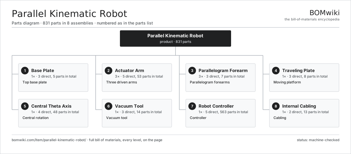
| # | Part | Qty | What it does |
|---|---|---|---|
| 1 | Base Plate 3 parts | 1× | Top base plate |
| 2 | Actuator Arm 5 parts | 3× | Three driven arms |
| 3 | Parallelogram Forearm 3 parts | 3× | Parallelogram forearms |
| 4 | Traveling Plate 3 parts | 1× | Moving platform |
| 5 | Central Theta Axis 4 parts | 1× | Central rotation |
| 6 | Vacuum Tool 3 parts | 1× | Vacuum tool |
| 7 | Robot Controller 5 parts | 1× | Controller |
| 8 | Internal Cabling 2 parts | 1× | Cabling |
3D model
No 3D model yet. Have a CAD file of this? Add a 3D model — STL renders right on this page; STEP, FreeCAD, and OpenSCAD sources are welcome too (openly licensed, like all 3D models on BOMwiki).
Build & assembly graph
expand / collapse · shared sub-assemblies converge · links to related products · est. labourTap an assembly to expand/collapse · tap a part to open it · use “Open page” for any node · drag to pan, scroll to zoom.
Bill of materials for Parallel Kinematic Robot
8 top-level lines · 67 rows shown · 831 parts total · indented to 3 levels| # | Item / sub-assembly | Part no. | Qty/assy | Ext. qty | Parts | Type |
|---|---|---|---|---|---|---|
| 1 | Base Plate 3 parts | parallel-kinematic-robot-base-plate | 1× | 1 | 5 | assembly |
| 1.1 | Base Casting | parallel-kinematic-robot-base-casting | 1× | 1 | · | part |
| 1.2 | Actuator Mount Flange | parallel-kinematic-robot-mount-flange | 3× | 3 | · | part |
| 1.3 | Fastener Set | fastener-set | 1× | 1 | · | part |
| 2 | Actuator Arm 5 parts | parallel-kinematic-robot-actuator-arm | 3× | 3 | 53 | assembly |
| 2.1 | Servo Motor 4 parts | servo-motor | 1× | 3 | 24 | assembly |
| 2.1.1 | Stator Assembly 3 parts + deeper › | stator-assembly | 1× | 3 | 3 | assembly |
| 2.1.2 | Rotor Assembly 4 parts + deeper › | rotor-assembly | 1× | 3 | 19 | assembly |
| 2.1.3 | Encoder | encoder | 1× | 3 | · | part |
| 2.1.4 | Motor Housing | motor-housing | 1× | 3 | · | part |
| 2.2 | Planetary Reducer 4 parts | parallel-kinematic-robot-reducer | 1× | 3 | 5 | assembly |
| 2.2.1 | Gearbox Housing | gearbox-housing | 1× | 3 | · | part |
| 2.2.2 | Helical Gear Pair | gear-pair | 1× | 3 | · | part |
| 2.2.3 | Planet Carrier | parallel-kinematic-robot-planet-carrier | 1× | 3 | · | part |
| 2.2.4 | Ball Bearing | ball-bearing | 2× | 6 | · | part |
| 2.3 | Carbon Upper Arm | parallel-kinematic-robot-upper-arm | 1× | 3 | · | part |
| 2.4 | Absolute Encoder 2 parts | parallel-kinematic-robot-encoder | 1× | 3 | 21 | assembly |
| 2.4.1 | Bare PCB | pcb-bare | 1× | 3 | · | part |
| 2.4.2 | SMD Passive (R/C/L) | smd-passives | 20× | 60 | · | part |
| 2.5 | Ball Bearing | ball-bearing | 2× | 6 | · | part |
| 3 | Parallelogram Forearm 3 parts | parallel-kinematic-robot-forearm | 3× | 3 | 7 | assembly |
| 3.1 | Carbon-Fibre Rod | parallel-kinematic-robot-cf-rod | 2× | 6 | · | part |
| 3.2 | Ball Joint | parallel-kinematic-robot-ball-joint | 4× | 12 | · | part |
| 3.3 | Tension Spring | parallel-kinematic-robot-tension-spring | 1× | 3 | · | part |
| 4 | Traveling Plate 3 parts | parallel-kinematic-robot-traveling-plate | 1× | 1 | 8 | assembly |
| 4.1 | Plate Body | parallel-kinematic-robot-plate-body | 1× | 1 | · | part |
| 4.2 | Ball Joint | parallel-kinematic-robot-ball-joint | 6× | 6 | · | part |
| 4.3 | Tool Mount | parallel-kinematic-robot-tool-mount | 1× | 1 | · | part |
| 5 | Central Theta Axis 4 parts | parallel-kinematic-robot-theta-axis | 1× | 1 | 48 | assembly |
| 5.1 | Servo Motor 4 parts | servo-motor | 1× | 1 | 24 | assembly |
| 5.1.1 | Stator Assembly 3 parts + deeper › | stator-assembly | 1× | 1 | 3 | assembly |
| 5.1.2 | Rotor Assembly 4 parts + deeper › | rotor-assembly | 1× | 1 | 19 | assembly |
| 5.1.3 | Encoder | encoder | 1× | 1 | · | part |
| 5.1.4 | Motor Housing | motor-housing | 1× | 1 | · | part |
| 5.2 | Telescoping Shaft | parallel-kinematic-robot-telescoping-shaft | 1× | 1 | · | part |
| 5.3 | Universal Joint | parallel-kinematic-robot-u-joint | 2× | 2 | · | part |
| 5.4 | Absolute Encoder 2 parts | parallel-kinematic-robot-encoder | 1× | 1 | 21 | assembly |
| 5.4.1 | Bare PCB | pcb-bare | 1× | 1 | · | part |
| 5.4.2 | SMD Passive (R/C/L) | smd-passives | 20× | 20 | · | part |
| 6 | Vacuum Tool 3 parts | parallel-kinematic-robot-gripper | 1× | 1 | 14 | assembly |
| 6.1 | Suction Cup | parallel-kinematic-robot-suction-cup | 1× | 1 | · | part |
| 6.2 | Venturi Ejector | parallel-kinematic-robot-venturi | 1× | 1 | · | part |
| 6.3 | Vacuum Sensor 3 parts | parallel-kinematic-robot-vacuum-sensor | 1× | 1 | 12 | assembly |
| 6.3.1 | Pressure Sensor | pressure-sensor | 1× | 1 | · | part |
| 6.3.2 | Bare PCB | pcb-bare | 1× | 1 | · | part |
| 6.3.3 | SMD Passive (R/C/L) | smd-passives | 10× | 10 | · | part |
| 7 | Robot Controller 5 parts | parallel-kinematic-robot-controller | 1× | 1 | 563 | assembly |
| 7.1 | Controller Main Board 4 parts | parallel-kinematic-robot-main-board | 1× | 1 | 213 | assembly |
| 7.1.1 | Bare PCB | pcb-bare | 1× | 1 | · | part |
| 7.1.2 | Microcontroller | mcu | 2× | 2 | · | part |
| 7.1.3 | SMD Passive (R/C/L) | smd-passives | 200× | 200 | · | part |
| 7.1.4 | Connector | connector | 10× | 10 | · | part |
| 7.2 | Servo Drive 5 parts | parallel-kinematic-robot-servo-drive | 4× | 4 | 81 | assembly |
| 7.2.1 | Bare PCB | pcb-bare | 1× | 4 | · | part |
| 7.2.2 | Power MOSFET | mosfet | 6× | 24 | · | part |
| 7.2.3 | Gate Driver IC | gate-driver-ic | 1× | 4 | · | part |
| 7.2.4 | SMD Passive (R/C/L) | smd-passives | 70× | 280 | · | part |
| 7.2.5 | Connector | connector | 3× | 12 | · | part |
| 7.3 | Power Supply | power-supply | 1× | 1 | · | part |
| 7.4 | Conveyor Tracker 3 parts | parallel-kinematic-robot-conveyor-tracker | 1× | 1 | 24 | assembly |
| 7.4.1 | Bare PCB | pcb-bare | 1× | 1 | · | part |
| 7.4.2 | Absolute Encoder 2 parts + deeper › | parallel-kinematic-robot-encoder | 1× | 1 | 21 | assembly |
| 7.4.3 | Connector | connector | 2× | 2 | · | part |
| 7.5 | Control Enclosure | parallel-kinematic-robot-control-enclosure | 1× | 1 | · | part |
| 8 | Internal Cabling 2 parts | parallel-kinematic-robot-cabling | 1× | 1 | 13 | assembly |
| 8.1 | Wire Bundle | wire-bundle | 1× | 1 | · | part |
| 8.2 | Connector | connector | 12× | 12 | · | part |
Related products
same domain, ranked by shared parts Pick-and-Place Robot
838 parts · shares 5 with this page
Laser Welding Robot
1,294 parts · shares 4 with this page
Machine Tending Robot
1,174 parts · shares 4 with this page
Pick-and-Place Robot
838 parts · shares 5 with this page
Laser Welding Robot
1,294 parts · shares 4 with this page
Machine Tending Robot
1,174 parts · shares 4 with this page
 Arc Welding Robot
1,532 parts · shares 4 with this page
Arc Welding Robot
1,532 parts · shares 4 with this page
 Seven-Axis Industrial Robot
1,450 parts · shares 4 with this page
Seven-Axis Industrial Robot
1,450 parts · shares 4 with this page
Sourcing: possible vendors
Prices, MOQ, and lead times are algorithmic estimates, not quotes, and not claims about these companies. Company mappings are curated by keyword; est. price band $3k–$500k. How estimates work| Vendor | HQ | Specialty | MOQ | Lead time |
|---|---|---|---|---|
|
🇯🇵Fanuc
fanuc.com ↗
|
Oshino, JP | Industrial robots & CNC | 20 units | 10–18 wks |
| abb.com ↗ | Zurich, CH | Industrial robots | 20 units | 10–18 wks |
|
🇯🇵Yaskawa
yaskawa.com ↗
|
Kitakyushu, JP | Robots & motion | 20 units | 10–18 wks |
|
🇩🇪KUKA
kuka.com ↗
|
Augsburg, DE | Industrial robots | 20 units | 10–18 wks |
| universal-robots.com ↗ | Odense, DK | Collaborative robots | 20 units | 10–18 wks |
914-word article