Mobile Manipulator
ProductOverview
A mobile manipulator merges two robots into one platform: an autonomous mobile base that drives itself around a facility, and an articulated arm mounted on top that picks, places, and manipulates objects once it arrives. The combination removes the fixed work envelope of a bolted-down arm, the robot can fetch a part from a rack in one aisle, carry it across the floor, and load it into a machine in another. It is used for machine tending, lab automation, and warehouse pick-and-place where the items and stations are spread out rather than fed to a single station.
How it works
The Mobile Base is a differential-drive chassis: two geared Drive Wheel Module modules provide motive force and steering by turning at different speeds, and four corner casters carry the rest of the weight. Two 360° Safety LiDAR scanners and an IMU feed a SLAM stack that maps the building, localises the robot, and enforces protective stops if a person steps into its path. The whole base is commanded by the Onboard Computer, a GPU-class SoC paired with a real-time safety MCU.
On top sits the Six-Axis Arm, six identical Servo Joint modules separated by cast links. Each joint is a Servo Motor driving a Harmonic Reducer strain-wave gearbox through an encoder, giving the arm 0.05 mm repeatability. The wrist carries a Parallel Gripper, a two-finger electric gripper with force feedback, and the Perception Suite suite of colour cameras plus a Depth Camera stereo module that builds a 3D view for locating objects and guiding the grasp.
Energy comes from a swappable Battery Pack Li-ion pack with its own management board, sized for a full shift. A Controller Cabinet cabinet holds the arm servo drives, the base motor driver, and a redundant safety board that limits arm force and speed whenever a person is nearby. A single Wiring Harness ties the base, arm, sensors, and compute together so the platform behaves as one coordinated machine.
Mobile Manipulator parts and their functions
8 top-level parts · 1,307 parts in total · full bill of materials below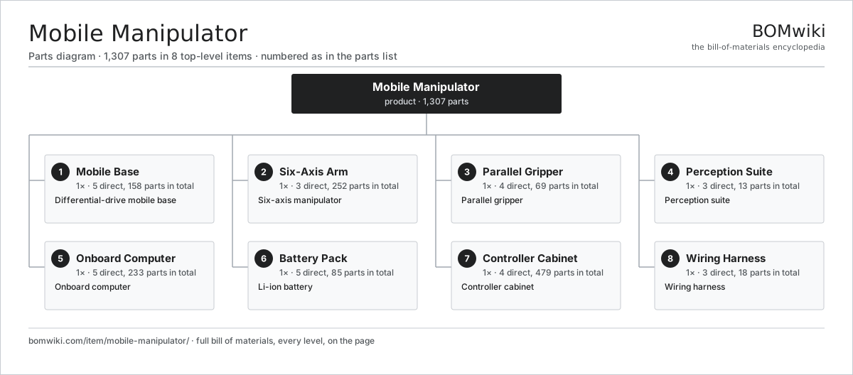
| # | Part | Qty | What it does |
|---|---|---|---|
| 1 | Mobile Base 5 parts | 1× | Differential-drive mobile base |
| 2 | Six-Axis Arm 3 parts | 1× | Six-axis manipulator |
| 3 | Parallel Gripper 4 parts | 1× | Parallel gripper |
| 4 | Perception Suite 3 parts | 1× | Perception suite |
| 5 | Onboard Computer 5 parts | 1× | Onboard computer |
| 6 | Battery Pack 5 parts | 1× | Li-ion battery |
| 7 | Controller Cabinet 4 parts | 1× | Controller cabinet |
| 8 | Wiring Harness 3 parts | 1× | Wiring harness |
Diagrams & photos


3D model
No 3D model yet. Have a CAD file of this? Add a 3D model. STL renders right on this page; STEP, FreeCAD, and OpenSCAD sources are welcome too (openly licensed, like all 3D models on BOMwiki).
Build & assembly graph
expand / collapse · shared sub-assemblies converge · links to related products · est. labourTap an assembly to expand/collapse · tap a part to open it · use “Open page” for any node · drag to pan, scroll to zoom.
Bill of materials for Mobile Manipulator
8 top-level lines · 84 rows shown · 1,307 parts total · indented to 3 levels| # | Item / sub-assembly | Part no. | Qty/assy | Ext. qty | Parts | Type |
|---|---|---|---|---|---|---|
| 1 | Mobile Base 5 parts | mobile-manipulator-base | 1× | 1 | 158 | assembly |
| 1.1 | Base Chassis 3 parts | mobile-manipulator-chassis | 1× | 1 | 3 | assembly |
| 1.1.1 | Base Weldment | mobile-manipulator-weldment | 1× | 1 | · | part |
| 1.1.2 | Base Cover | mobile-manipulator-cover | 1× | 1 | · | part |
| 1.1.3 | Fastener Set | fastener-set | 1× | 1 | · | part |
| 1.2 | Drive Wheel Module 4 parts | mobile-manipulator-drive-wheel | 2× | 2 | 42 | assembly |
| 1.2.1 | BLDC Wheel Motor 6 parts + deeper › | mobile-manipulator-wheel-motor | 1× | 2 | 36 | assembly |
| 1.2.2 | Wheel Gearbox 3 parts + deeper › | mobile-manipulator-wheel-gearbox | 1× | 2 | 4 | assembly |
| 1.2.3 | Drive Wheel | mobile-manipulator-wheel | 1× | 2 | · | part |
| 1.2.4 | Encoder | encoder | 1× | 2 | · | part |
| 1.3 | Swivel Caster 3 parts | mobile-manipulator-caster | 4× | 4 | 4 | assembly |
| 1.3.1 | Caster Fork | mobile-manipulator-caster-fork | 1× | 4 | · | part |
| 1.3.2 | Caster Wheel | mobile-manipulator-caster-wheel | 1× | 4 | · | part |
| 1.3.3 | Ball Bearing | ball-bearing | 2× | 8 | · | part |
| 1.4 | Safety LiDAR 4 parts | mobile-manipulator-base-lidar | 2× | 2 | 27 | assembly |
| 1.4.1 | LiDAR Optics Module | mobile-manipulator-lidar-optics | 1× | 2 | · | part |
| 1.4.2 | Servo Motor 4 parts + deeper › | servo-motor | 1× | 2 | 24 | assembly |
| 1.4.3 | Bare PCB | pcb-bare | 1× | 2 | · | part |
| 1.4.4 | Encoder | encoder | 1× | 2 | · | part |
| 1.5 | Base IMU | mobile-manipulator-base-imu | 1× | 1 | · | part |
| 2 | Six-Axis Arm 3 parts | mobile-manipulator-arm | 1× | 1 | 252 | assembly |
| 2.1 | Servo Joint 4 parts | mobile-manipulator-joint | 6× | 6 | 41 | assembly |
| 2.1.1 | Servo Motor 5 parts + deeper › | mobile-manipulator-servo-motor | 1× | 6 | 32 | assembly |
| 2.1.2 | Harmonic Reducer 3 parts + deeper › | mobile-manipulator-reducer | 1× | 6 | 4 | assembly |
| 2.1.3 | Joint Encoder 2 parts + deeper › | mobile-manipulator-encoder | 1× | 6 | 3 | assembly |
| 2.1.4 | Ball Bearing | ball-bearing | 2× | 12 | · | part |
| 2.2 | Arm Link | mobile-manipulator-link | 5× | 5 | · | part |
| 2.3 | Shoulder Mount | mobile-manipulator-arm-base | 1× | 1 | · | part |
| 3 | Parallel Gripper 4 parts | mobile-manipulator-gripper | 1× | 1 | 69 | assembly |
| 3.1 | Gripper Servo 3 parts | mobile-manipulator-gripper-motor | 1× | 1 | 23 | assembly |
| 3.1.1 | Stator Assembly 3 parts + deeper › | stator-assembly | 1× | 1 | 3 | assembly |
| 3.1.2 | Rotor Assembly 4 parts + deeper › | rotor-assembly | 1× | 1 | 19 | assembly |
| 3.1.3 | Motor Housing | motor-housing | 1× | 1 | · | part |
| 3.2 | Gripper Spindle | mobile-manipulator-gripper-screw | 1× | 1 | · | part |
| 3.3 | Gripper Finger | mobile-manipulator-finger | 2× | 2 | · | part |
| 3.4 | Gripper Board 4 parts | mobile-manipulator-gripper-board | 1× | 1 | 43 | assembly |
| 3.4.1 | Bare PCB | pcb-bare | 1× | 1 | · | part |
| 3.4.2 | Microcontroller | mcu | 1× | 1 | · | part |
| 3.4.3 | SMD Passive (R/C/L) | smd-passives | 40× | 40 | · | part |
| 3.4.4 | Connector | connector | 1× | 1 | · | part |
| 4 | Perception Suite 3 parts | mobile-manipulator-sensors | 1× | 1 | 13 | assembly |
| 4.1 | Camera Module 3 parts | mobile-manipulator-camera | 2× | 2 | 3 | assembly |
| 4.1.1 | CMOS Image Sensor | image-sensor | 1× | 2 | · | part |
| 4.1.2 | Lens Assembly | camera-lens | 1× | 2 | · | part |
| 4.1.3 | Bare PCB | pcb-bare | 1× | 2 | · | part |
| 4.2 | Depth Camera 4 parts | mobile-manipulator-depth-camera | 1× | 1 | 6 | assembly |
| 4.2.1 | CMOS Image Sensor | image-sensor | 2× | 2 | · | part |
| 4.2.2 | Lens Assembly | camera-lens | 2× | 2 | · | part |
| 4.2.3 | IR Pattern Projector | mobile-manipulator-ir-projector | 1× | 1 | · | part |
| 4.2.4 | Bare PCB | pcb-bare | 1× | 1 | · | part |
| 4.3 | Wrist IMU | mobile-manipulator-arm-imu | 1× | 1 | · | part |
| 5 | Onboard Computer 5 parts | mobile-manipulator-computer | 1× | 1 | 233 | assembly |
| 5.1 | Bare PCB | pcb-bare | 1× | 1 | · | part |
| 5.2 | Compute SoC Module | soc-module | 1× | 1 | · | part |
| 5.3 | Microcontroller | mcu | 1× | 1 | · | part |
| 5.4 | SMD Passive (R/C/L) | smd-passives | 220× | 220 | · | part |
| 5.5 | Connector | connector | 10× | 10 | · | part |
| 6 | Battery Pack 5 parts | mobile-manipulator-battery | 1× | 1 | 85 | assembly |
| 6.1 | Li-ion Cell, 18650 | li-cell-18650 | 80× | 80 | · | part |
| 6.2 | BMS Board | bms-board | 1× | 1 | · | part |
| 6.3 | Battery Tray | mobile-manipulator-battery-tray | 1× | 1 | · | part |
| 6.4 | Fuse Box | fuse-box | 1× | 1 | · | part |
| 6.5 | Connector | connector | 2× | 2 | · | part |
| 7 | Controller Cabinet 4 parts | mobile-manipulator-controller | 1× | 1 | 479 | assembly |
| 7.1 | Servo Drive 4 parts | mobile-manipulator-servo-drive | 6× | 6 | 75 | assembly |
| 7.1.1 | Bare PCB | pcb-bare | 1× | 6 | · | part |
| 7.1.2 | IGBT Power Module | igbt-module | 1× | 6 | · | part |
| 7.1.3 | SMD Passive (R/C/L) | smd-passives | 70× | 420 | · | part |
| 7.1.4 | Connector | connector | 3× | 18 | · | part |
| 7.2 | Base Motor Driver 4 parts | mobile-manipulator-base-driver | 1× | 1 | 18 | assembly |
| 7.2.1 | Bare PCB | pcb-bare | 1× | 1 | · | part |
| 7.2.2 | Power MOSFET | mosfet | 12× | 12 | · | part |
| 7.2.3 | Microcontroller | mcu | 1× | 1 | · | part |
| 7.2.4 | Connector | connector | 4× | 4 | · | part |
| 7.3 | Safety Controller 4 parts | mobile-manipulator-safety-board | 1× | 1 | 10 | assembly |
| 7.3.1 | Bare PCB | pcb-bare | 1× | 1 | · | part |
| 7.3.2 | Microcontroller | mcu | 1× | 1 | · | part |
| 7.3.3 | Relay | relay | 4× | 4 | · | part |
| 7.3.4 | Connector | connector | 4× | 4 | · | part |
| 7.4 | Cabinet Frame | mobile-manipulator-cabinet-frame | 1× | 1 | · | part |
| 8 | Wiring Harness 3 parts | mobile-manipulator-harness | 1× | 1 | 18 | assembly |
| 8.1 | Wire Bundle | wire-bundle | 1× | 1 | · | part |
| 8.2 | Connector | connector | 16× | 16 | · | part |
| 8.3 | Fuse Box | fuse-box | 1× | 1 | · | part |
Something wrong in this list? Report a problem with this BOM.
Related products
same domain, ranked by shared parts AGV Mobile Robot
383 parts · shares 10 with this page
 Autonomous Mobile Robot (AMR)
627 parts · shares 6 with this page
Security Patrol Robot
582 parts · shares 6 with this page
 Sidewalk Delivery Robot
568 parts · shares 6 with this page
Quadruped Robot
1,080 parts · shares 6 with this page
 Humanoid Robot
3,158 parts · shares 6 with this page
Sourcing: possible vendors
Browse the supplier directory → Prices, MOQ, and lead times are algorithmic estimates, not quotes, and not claims about these companies. Company mappings are curated by keyword; est. price band $3k–$500k. How estimates work| Vendor | HQ | Specialty | MOQ | Lead time |
|---|---|---|---|---|
|
🇯🇵Fanuc
fanuc.com ↗
|
Oshino, JP | Industrial robots & CNC | 20 units | 10–18 wks |
| abb.com ↗ | Zurich, CH | Industrial robots | 20 units | 10–18 wks |
|
🇯🇵Yaskawa
yaskawa.com ↗
|
Kitakyushu, JP | Robots & motion | 20 units | 10–18 wks |
|
🇩🇪KUKA
kuka.com ↗
|
Augsburg, DE | Industrial robots | 20 units | 10–18 wks |
| universal-robots.com ↗ | Odense, DK | Collaborative robots | 20 units | 10–18 wks |
352-word article