Vision-Guided Robot
ProductOverview
A vision-guided robot finds parts before it picks them. An ordinary industrial robot repeats a fixed path and needs every part presented in exactly the same place. This robot instead looks at the work area with a camera, figures out where each part actually is and how it is oriented, and adjusts its pick to match. That difference removes the most expensive part of automation: the fixturing and feeders that would otherwise have to present parts perfectly. The classic application is bin picking, reaching into a tote of parts dumped in at random, but the same capability handles parts arriving in trays, on a conveyor, or in any arrangement that is not precisely controlled.
How it works
The two halves of the system are an arm and an eye. The Six-Axis Arm is a standard six-axis articulated robot: six Servo Joint axes give it full freedom to reach any position and any orientation, which it needs because a part lying at a random angle has to be approached from a random direction. Each joint pairs a Servo Motor with a RV Reducer, a cycloidal RV reducer chosen at the base joints for its shock resistance and stiffness under the long lever of an extended arm. The wrist is a compact Three-Roll Wrist that packs the last three axes into a small head so the tool can twist into tight orientations.
The eye is the 3D Vision System, a 3D structured-light head. Two Industrial Camera units form a stereo pair, and a Pattern Projector throws a known fringe pattern onto the parts. Plain stereo struggles on smooth, featureless surfaces because there is nothing to match between the two images, so the projected pattern gives the cameras texture to triangulate against. From the two images the system builds a dense 3D point cloud of everything in the field of view.
Vision processing
The point cloud is meaningless until something interprets it, which is the job of the Vision Computer. Its Vision Processor Board runs a pipeline that segments the cloud into individual parts, matches each against a stored CAD model, and computes the exact 6-degree-of-freedom pose of every graspable part. It then chooses which part to pick first, usually the topmost and least obstructed one, and which grasp avoids collisions with the bin walls and neighbouring parts. The result is a pick pose handed to the robot. The whole loop, capture to pose, takes a fraction of a second and repeats for every pick because the pile changes after each one.
Calibration and lighting
The vision system reports positions in camera coordinates, but the robot moves in its own coordinates, so the two must be tied together. That is hand-eye calibration: a Calibration Target dot grid is shown to the camera from several robot poses, and the software solves for the transform between camera and robot. Get this wrong and the robot reaches confidently to the wrong place. Lighting is just as important. The Structured Lighting module surrounds the work area with strobed LED Ring Light and Bar Light units, removing glare and shadow that would otherwise create false depth, and a controller strobes them in step with the camera exposure to freeze any motion.
Gripping
Once the robot reaches a part it has to hold it, and because parts arrive in different sizes and the grasp width varies, this robot uses an Adaptive Gripper, a servo parallel gripper rather than a fixed-width tool. The Gripper Drive closes the jaws to the width the vision system measured, and a Grip Force Sensor limits the clamp force so a thin or delicate part is held firmly without being crushed. The Gripper Finger jaws are the one part shaped for a specific job and are swapped when the part family changes.
Control and structure
The arm itself is run by the Robot Controller, which closes the servo loops through a Servo Drive per axis and enforces speed and zone limits through a redundant Safety Board. The controller takes a target pose from the vision computer and plans a collision-free path to it, then executes the pick and the place. The arm and the camera frame both mount on a rigid Pedestal Base so the calibrated relationship between eye and hand does not drift, and all the power and feedback wiring runs through the Internal Cabling bundle.
Materials and variants
Arm links are cast aluminium or iron at the base, sized for stiffness rather than light weight, and the reducers run alloy-steel internals in an oil bath. Camera lenses are low-distortion fixed-focal-length glass, because a zoom would lose calibration. Variants differ mainly in the vision head: some use a single 3D snapshot sensor, others a laser line scanner that sweeps across the parts, and high-speed lines mount the camera on the wrist so it can look into deep bins. Larger systems scale the arm to 20 kg payloads for handling castings and forgings, while electronics versions use a small SCARA under a fixed overhead camera.
Use
Vision guidance shows up wherever parts cannot be fixtured cheaply: machine loading from bulk bins, assembly of components delivered loose, kitting, and quality sorting. It is slower than a blind pick-and-place because every cycle includes a look, but it eliminates the feeders and trays that blind automation depends on, which is often the larger cost. As parts get more varied and production runs get shorter, the ability to simply look and adapt becomes more valuable than raw cycle speed.
Vision-Guided Robot parts and their functions
8 top-level parts · 1,735 parts in total · full bill of materials below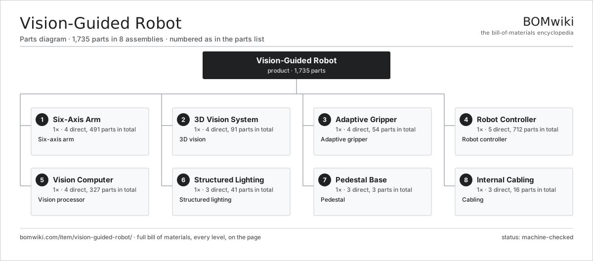
| # | Part | Qty | What it does |
|---|---|---|---|
| 1 | Six-Axis Arm 4 parts | 1× | Six-axis arm |
| 2 | 3D Vision System 4 parts | 1× | 3D vision |
| 3 | Adaptive Gripper 4 parts | 1× | Adaptive gripper |
| 4 | Robot Controller 5 parts | 1× | Robot controller |
| 5 | Vision Computer 4 parts | 1× | Vision processor |
| 6 | Structured Lighting 3 parts | 1× | Structured lighting |
| 7 | Pedestal Base 3 parts | 1× | Pedestal |
| 8 | Internal Cabling 3 parts | 1× | Cabling |
3D model
No 3D model yet. Have a CAD file of this? Add a 3D model — STL renders right on this page; STEP, FreeCAD, and OpenSCAD sources are welcome too (openly licensed, like all 3D models on BOMwiki).
Build & assembly graph
expand / collapse · shared sub-assemblies converge · links to related products · est. labourTap an assembly to expand/collapse · tap a part to open it · use “Open page” for any node · drag to pan, scroll to zoom.
Bill of materials for Vision-Guided Robot
8 top-level lines · 83 rows shown · 1,735 parts total · indented to 3 levels| # | Item / sub-assembly | Part no. | Qty/assy | Ext. qty | Parts | Type |
|---|---|---|---|---|---|---|
| 1 | Six-Axis Arm 4 parts | vision-guided-robot-arm | 1× | 1 | 491 | assembly |
| 1.1 | Servo Joint 5 parts | vision-guided-robot-joint | 6× | 6 | 54 | assembly |
| 1.1.1 | Servo Motor 4 parts + deeper › | servo-motor | 1× | 6 | 24 | assembly |
| 1.1.2 | RV Reducer 4 parts + deeper › | vision-guided-robot-reducer | 1× | 6 | 6 | assembly |
| 1.1.3 | Holding Brake | vision-guided-robot-brake | 1× | 6 | · | part |
| 1.1.4 | Absolute Encoder 2 parts + deeper › | vision-guided-robot-encoder | 1× | 6 | 21 | assembly |
| 1.1.5 | Ball Bearing | ball-bearing | 2× | 12 | · | part |
| 1.2 | Lower Arm Casting | vision-guided-robot-link-lower | 1× | 1 | · | part |
| 1.3 | Upper Arm Casting | vision-guided-robot-link-upper | 1× | 1 | · | part |
| 1.4 | Three-Roll Wrist 3 parts | vision-guided-robot-wrist | 1× | 1 | 165 | assembly |
| 1.4.1 | Servo Joint 5 parts + deeper › | vision-guided-robot-joint | 3× | 3 | 54 | assembly |
| 1.4.2 | Wrist Housing | vision-guided-robot-wrist-housing | 1× | 1 | · | part |
| 1.4.3 | Helical Gear Pair | gear-pair | 2× | 2 | · | part |
| 2 | 3D Vision System 4 parts | vision-guided-robot-vision-system | 1× | 1 | 91 | assembly |
| 2.1 | Industrial Camera 4 parts | vision-guided-robot-camera | 2× | 2 | 43 | assembly |
| 2.1.1 | CMOS Image Sensor | vision-guided-robot-image-sensor | 1× | 2 | · | part |
| 2.1.2 | Machine Vision Lens | vision-guided-robot-lens | 1× | 2 | · | part |
| 2.1.3 | Bare PCB | pcb-bare | 1× | 2 | · | part |
| 2.1.4 | SMD Passive (R/C/L) | smd-passives | 40× | 80 | · | part |
| 2.2 | Pattern Projector 3 parts | vision-guided-robot-projector | 1× | 1 | 3 | assembly |
| 2.2.1 | LED Array | vision-guided-robot-led-array | 1× | 1 | · | part |
| 2.2.2 | Pattern Slide | vision-guided-robot-pattern-slide | 1× | 1 | · | part |
| 2.2.3 | Machine Vision Lens | vision-guided-robot-lens | 1× | 1 | · | part |
| 2.3 | Camera Mount | vision-guided-robot-camera-mount | 1× | 1 | · | part |
| 2.4 | Calibration Target | vision-guided-robot-calibration-target | 1× | 1 | · | part |
| 3 | Adaptive Gripper 4 parts | vision-guided-robot-gripper | 1× | 1 | 54 | assembly |
| 3.1 | Gripper Finger | vision-guided-robot-gripper-finger | 2× | 2 | · | part |
| 3.2 | Gripper Drive 4 parts | vision-guided-robot-gripper-drive | 1× | 1 | 48 | assembly |
| 3.2.1 | Servo Motor 4 parts + deeper › | servo-motor | 1× | 1 | 24 | assembly |
| 3.2.2 | Ball Screw | ball-screw | 1× | 1 | · | part |
| 3.2.3 | Linear Guide Rail | linear-guide | 2× | 2 | · | part |
| 3.2.4 | Absolute Encoder 2 parts + deeper › | vision-guided-robot-encoder | 1× | 1 | 21 | assembly |
| 3.3 | Grip Force Sensor 2 parts | vision-guided-robot-force-sensor | 1× | 1 | 3 | assembly |
| 3.3.1 | Strain Gauge | vision-guided-robot-strain-gauge | 2× | 2 | · | part |
| 3.3.2 | Bare PCB | pcb-bare | 1× | 1 | · | part |
| 3.4 | Gripper Body | vision-guided-robot-gripper-body | 1× | 1 | · | part |
| 4 | Robot Controller 5 parts | vision-guided-robot-controller | 1× | 1 | 712 | assembly |
| 4.1 | Controller Main Board 4 parts | vision-guided-robot-main-board | 1× | 1 | 213 | assembly |
| 4.1.1 | Bare PCB | pcb-bare | 1× | 1 | · | part |
| 4.1.2 | Microcontroller | mcu | 2× | 2 | · | part |
| 4.1.3 | SMD Passive (R/C/L) | smd-passives | 200× | 200 | · | part |
| 4.1.4 | Connector | connector | 10× | 10 | · | part |
| 4.2 | Servo Drive 5 parts | vision-guided-robot-servo-drive | 6× | 6 | 81 | assembly |
| 4.2.1 | Bare PCB | pcb-bare | 1× | 6 | · | part |
| 4.2.2 | Power MOSFET | mosfet | 6× | 36 | · | part |
| 4.2.3 | Gate Driver IC | gate-driver-ic | 1× | 6 | · | part |
| 4.2.4 | SMD Passive (R/C/L) | smd-passives | 70× | 420 | · | part |
| 4.2.5 | Connector | connector | 3× | 18 | · | part |
| 4.3 | Power Supply | power-supply | 1× | 1 | · | part |
| 4.4 | Safety Board 4 parts | vision-guided-robot-safety-board | 1× | 1 | 11 | assembly |
| 4.4.1 | Bare PCB | pcb-bare | 1× | 1 | · | part |
| 4.4.2 | Microcontroller | mcu | 2× | 2 | · | part |
| 4.4.3 | Relay | relay | 4× | 4 | · | part |
| 4.4.4 | Connector | connector | 4× | 4 | · | part |
| 4.5 | Control Enclosure | vision-guided-robot-control-enclosure | 1× | 1 | · | part |
| 5 | Vision Computer 4 parts | vision-guided-robot-vision-computer | 1× | 1 | 327 | assembly |
| 5.1 | Vision Processor Board 4 parts | vision-guided-robot-vision-board | 1× | 1 | 260 | assembly |
| 5.1.1 | Bare PCB | pcb-bare | 1× | 1 | · | part |
| 5.1.2 | Microcontroller | mcu | 1× | 1 | · | part |
| 5.1.3 | SMD Passive (R/C/L) | smd-passives | 250× | 250 | · | part |
| 5.1.4 | Connector | connector | 8× | 8 | · | part |
| 5.2 | Frame Grabber 3 parts | vision-guided-robot-frame-grabber | 1× | 1 | 65 | assembly |
| 5.2.1 | Bare PCB | pcb-bare | 1× | 1 | · | part |
| 5.2.2 | SMD Passive (R/C/L) | smd-passives | 60× | 60 | · | part |
| 5.2.3 | Connector | connector | 4× | 4 | · | part |
| 5.3 | Power Supply | power-supply | 1× | 1 | · | part |
| 5.4 | PC Enclosure | vision-guided-robot-pc-enclosure | 1× | 1 | · | part |
| 6 | Structured Lighting 3 parts | vision-guided-robot-lighting | 1× | 1 | 41 | assembly |
| 6.1 | Ring Light | vision-guided-robot-ring-light | 1× | 1 | · | part |
| 6.2 | Bar Light | vision-guided-robot-bar-light | 2× | 2 | · | part |
| 6.3 | Light Controller 4 parts | vision-guided-robot-light-controller | 1× | 1 | 38 | assembly |
| 6.3.1 | Bare PCB | pcb-bare | 1× | 1 | · | part |
| 6.3.2 | Power MOSFET | mosfet | 4× | 4 | · | part |
| 6.3.3 | SMD Passive (R/C/L) | smd-passives | 30× | 30 | · | part |
| 6.3.4 | Connector | connector | 3× | 3 | · | part |
| 7 | Pedestal Base 3 parts | vision-guided-robot-base | 1× | 1 | 3 | assembly |
| 7.1 | Base Casting | vision-guided-robot-base-casting | 1× | 1 | · | part |
| 7.2 | Camera Frame | vision-guided-robot-camera-frame | 1× | 1 | · | part |
| 7.3 | Fastener Set | fastener-set | 1× | 1 | · | part |
| 8 | Internal Cabling 3 parts | vision-guided-robot-cabling | 1× | 1 | 16 | assembly |
| 8.1 | Wire Bundle | wire-bundle | 1× | 1 | · | part |
| 8.2 | Connector | connector | 14× | 14 | · | part |
| 8.3 | Cable Carrier | vision-guided-robot-cable-carrier | 1× | 1 | · | part |
Related products
same domain, ranked by shared parts Robotic Assembly Cell
1,746 parts · shares 5 with this page
Robotic Grinding Cell
1,419 parts · shares 5 with this page
Robotic Assembly Cell
1,746 parts · shares 5 with this page
Robotic Grinding Cell
1,419 parts · shares 5 with this page
 Pick-and-Place Robot
838 parts · shares 6 with this page
Pick-and-Place Robot
838 parts · shares 6 with this page
 Cartesian Pick Robot
781 parts · shares 4 with this page
Tote Handling Robot
1,042 parts · shares 4 with this page
Cartesian Pick Robot
781 parts · shares 4 with this page
Tote Handling Robot
1,042 parts · shares 4 with this page
Sourcing: possible vendors
Prices, MOQ, and lead times are algorithmic estimates, not quotes, and not claims about these companies. Company mappings are curated by keyword; est. price band $3k–$500k. How estimates work| Vendor | HQ | Specialty | MOQ | Lead time |
|---|---|---|---|---|
|
🇯🇵Fanuc
fanuc.com ↗
|
Oshino, JP | Industrial robots & CNC | 20 units | 10–18 wks |
| abb.com ↗ | Zurich, CH | Industrial robots | 20 units | 10–18 wks |
|
🇯🇵Yaskawa
yaskawa.com ↗
|
Kitakyushu, JP | Robots & motion | 20 units | 10–18 wks |
|
🇩🇪KUKA
kuka.com ↗
|
Augsburg, DE | Industrial robots | 20 units | 10–18 wks |
| universal-robots.com ↗ | Odense, DK | Collaborative robots | 20 units | 10–18 wks |
979-word article